Details on Procedure Space Constructions
Figure J.6. Deleting a Wire
J.5. Example Procedure
In the example of Procedure 13, the Start button is connected to the Initialize input of the State as is
required in all procedures. When entering a State through the Initialize pin, the State comes up in its
default condition.
In this example, a procedure will be constructed to put a pulse on the STM Bias voltage.
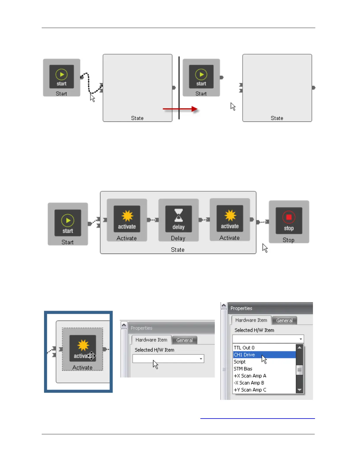
Figure J.7. Pulse Tip template
Clicking on first Activate icon will bring up a menu as shown below. Clicking on the dropdown box will
provide a list of every item that can be modified by the Procedure. This will include only those items that
have been placed on Workbench in Hardware Space. Scroll down the list of items that are shown and
select CH1 Drive. That is the output that is connected to the STM Bias voltage.
Figure J.8. Pulse Tip - set first Activate to CH1 Drive
A property box that represents all of the parameters that can be changed will be opened as shown below.
The individual parameters have been described in detail in Section 1, “Channel 1 Drive and Channel 2