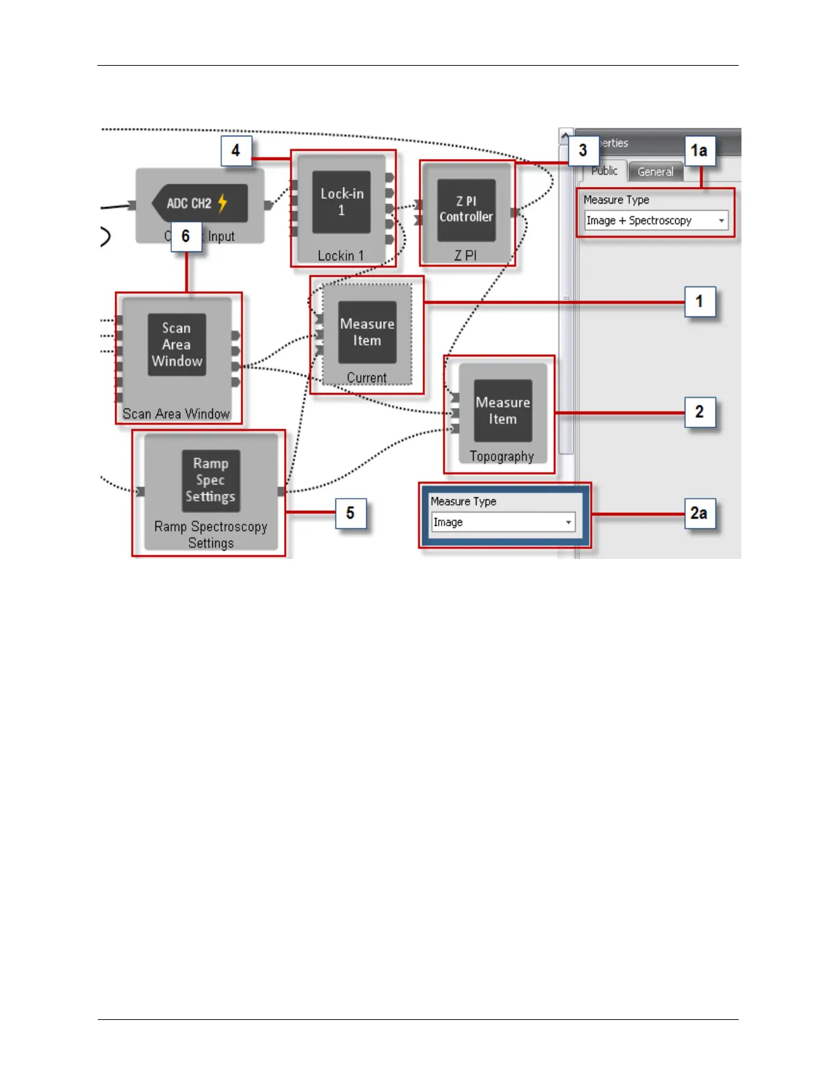
Figure A.10. Preconfigured STM Measure Items
1. Current: A Measure Item named Current is connected to the output of the Lock-in 1 (which gets its
signal from the Preamp Input).
a. Measure Type: Select the Current Measure Item to view its Measure Type property. It should be
set to Image + Spectroscopy so the Current signal is available for Imaging and Spectroscopy.
2. Topography: A Measure Item named Topography is connected to the output of the Z PI Feedback
Controller.
a. Measure Type: Select the Topography Measure Item to view its Measure Type property. It should
be set to Image so the Topography signal is available for Imaging.
3. Z PI: The output of the Z PI Feedback Controller is connected to the Topography Measure Item (as
well as the Input of the Scan Processor).
4. Lock-in 1: The output of the Lock-in 1 is connected to the Current Measure Item (as well as the Input
of the Z PI Feedback Controller).
5. Ramp Spectroscopy Settings: A Measure Item needs to be connected to the Ramp Spectroscopy
Settings if there will be Spectroscopy measurements on that Measure Item's signal.
6. Scan Area Window: A Measure Item needs to be connected to the Scan Settings output of the Scan
Area Window to allow the data channel to be properly parsed for display of the data in a 2-D window.