External Control Interface
Figure M.2. Typical reference setup on the Dashboard
M.2. Advanced Example
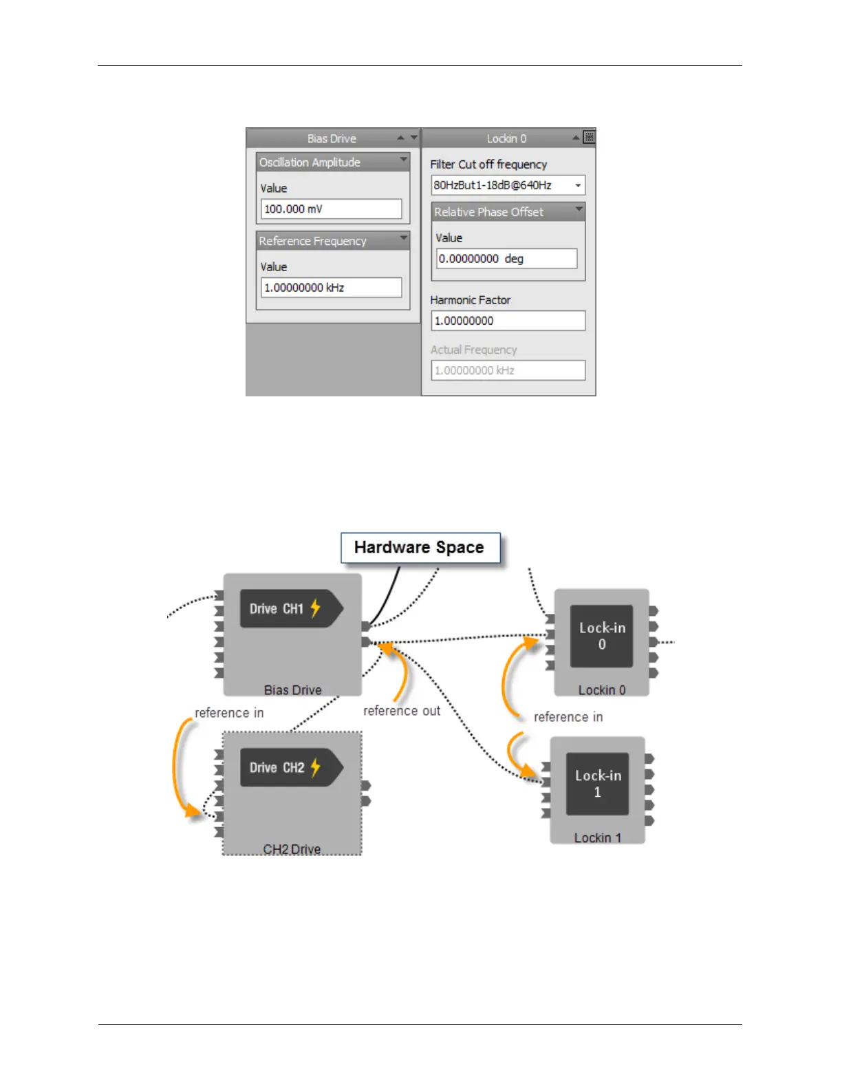
Referenced Frequencies do not only have to be between a Drive Output and Lockin Input. In the below
example, the CH1 Drive Reference Output pin is connected to the Reference Input pins of two lock-in
amplifiers as well as the CH2 Drive.
Figure M.3. Advanced reference setup in Hardware Space
Some advanced situations are shown below. CH1 Drive (Bias Drive) is the Master Oscillator. CH2 Drive is
set with a Harmonic Factor of 2, which gives a 2.000 kHz modulation. Lockin0 has a Harmonic Factor of 1
so it will detect signals at 1.000 kHz. Lockin1 has a Harmonic Factor of 2 and a Frequency Offset of 100
Hz so it will detect signals at 2.100 kHz.