Hardware Space Components
B.6.3. Using the Lock-in Amplifier for dI/dV Measurements
To use the Lock-in Amplifiers for spectroscopic measurements, such as dI/dV, the Frequency Offset
Input, the Phase Offset, and the Harmonic Factor parameters must be exposed on the dashboard as
shown below.
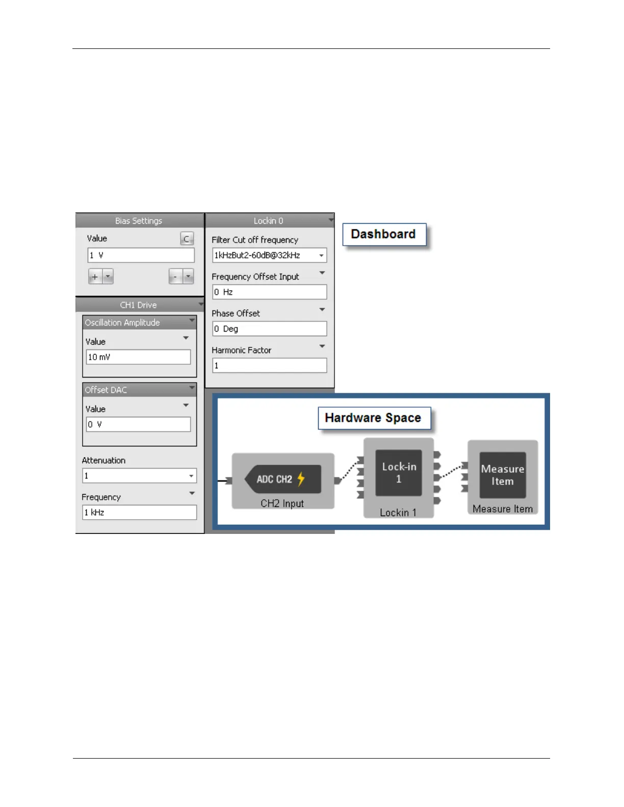
To begin, the parameters of the AC signal that will modulate the Bias Voltage are set on the dashboard.
In the example below, the oscillation will be a 1 kHz sine wave with an amplitude of 10 mV Peak. The
frequency used to modulate the Bias is entered in the Lock-in’s Frequency Offset Input data entry box.
The Harmonic Factor is set to 1. This configures the lock-in to detect signals on the reference frequency.
Figure B.14. Lock-in Amplifier used for dI/dV
Connecting a Measure Item to the Lock-in’s Receiver X output will allow the measurement of the amount
of signal present that is in sync with the reference oscillation frequency. The Phase Offset is adjusted to
compensate for the phase shift of the cables and other components outside of the R9. The Phase Offset
is adjusted until the signal level on the Receiver X output is maximized.
B.6.4. Lock-in Amplifiers Operating Independent of the High Speed
Inputs
The Lock-in Amplifiers can operate independent of the inputs, creating many new experimental
configurations.
In the example below, some new signal path options are shown. CH1 Input is measured after passing
through a filter and two virtual lock-in amplifiers detecting at two separate harmonics, while also
measuring the CH2 Input. Lock-in Amplifier 0 and Lock-in Amplifier 1 can take input from either the CH1
Input or CH2 Input.