The drift offsets and drift vectors are in physical units so you will have to calculate the appropriate nm/s
conversion if you choose the Manual Drift Correction.
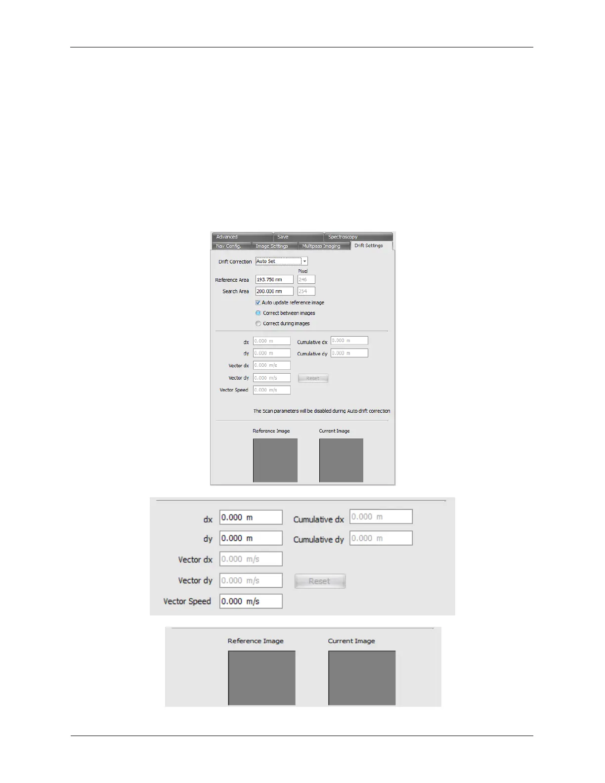
However we also have the Automatic Drift Correction. What this does is allows you to specify a
Reference Area (green box) on an image to select a portion of the image to track and compare and a
Search Area (blue box) around that Reference Area. After each image, the software will compare the
remembered Reference Image to each possible location inside the Search Area and return the offsets
from that location. The software will then use that information to calculate the XY Offset needed to put
that reference image in the same spot in the scan area as well as calculate the drift vectors for the
continuous drift correction. On the next image the reference area will again be compared inside the
search area to find the best spot. The XY Offsets will be adjusted and the drift vector will also be updated
if needed.
Figure 4.10. Automatic Drift Correction