Configuration Guide 160
Configuring 802.1Q VLAN Configuration Example
3.3 Network Topology
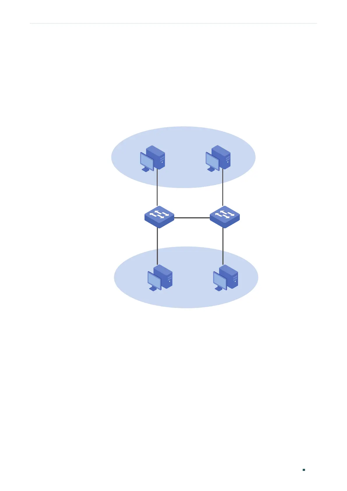
The figure below shows the network topology. Host A1 and Host A2 are used in
Department A, while Host B1 and Host B2 are used in Department B. Switch 1 and Switch
2 are located in two different places. Host A1 and Host B1 are connected to port 1/0/2 and
port 1/0/3 on Switch 1 respectively, while Host A2 and Host B2 are connected to port 1/0/6
and port 1/0/7 on Switch 2 respectively. Port 1/0/4 on Switch 1 is connected to port 1/0/8
on Switch 2.
Figure 3-1 Network Topology
VLAN 10
VLAN 20
Host A1 Host A2
Host B1
Host B2
Switch 1
Switch 2
Gi1/0/2
Gi1/0/3
Gi1/0/4
Gi1/0/6
Gi1/0/7
Gi1/0/8
Demonstrated with T1600G-52TS, the following sections provide configuration procedure
in two ways: using the GUI and using the CLI.
3.4 Using the GUI
The configurations of Switch 1 and Switch 2 are similar. The following introductions take
Switch 1 as an example.
1) Choose the menu VLAN > 802.1Q VLAN > VLAN Config and click Create to load the
following page. Create VLAN 10 with the description of Department-A. Add port 1/0/2
as an untagged port and port 1/0/4 as a tagged port to VLAN 10. Then click Apply.