Zynq-7000 AP SoC and 7 Series FPGAs MIS v4.1 239
UG586 November 30, 2016
www.xilinx.com
Chapter 1: DDR3 and DDR2 SDRAM Memory Interface Solution
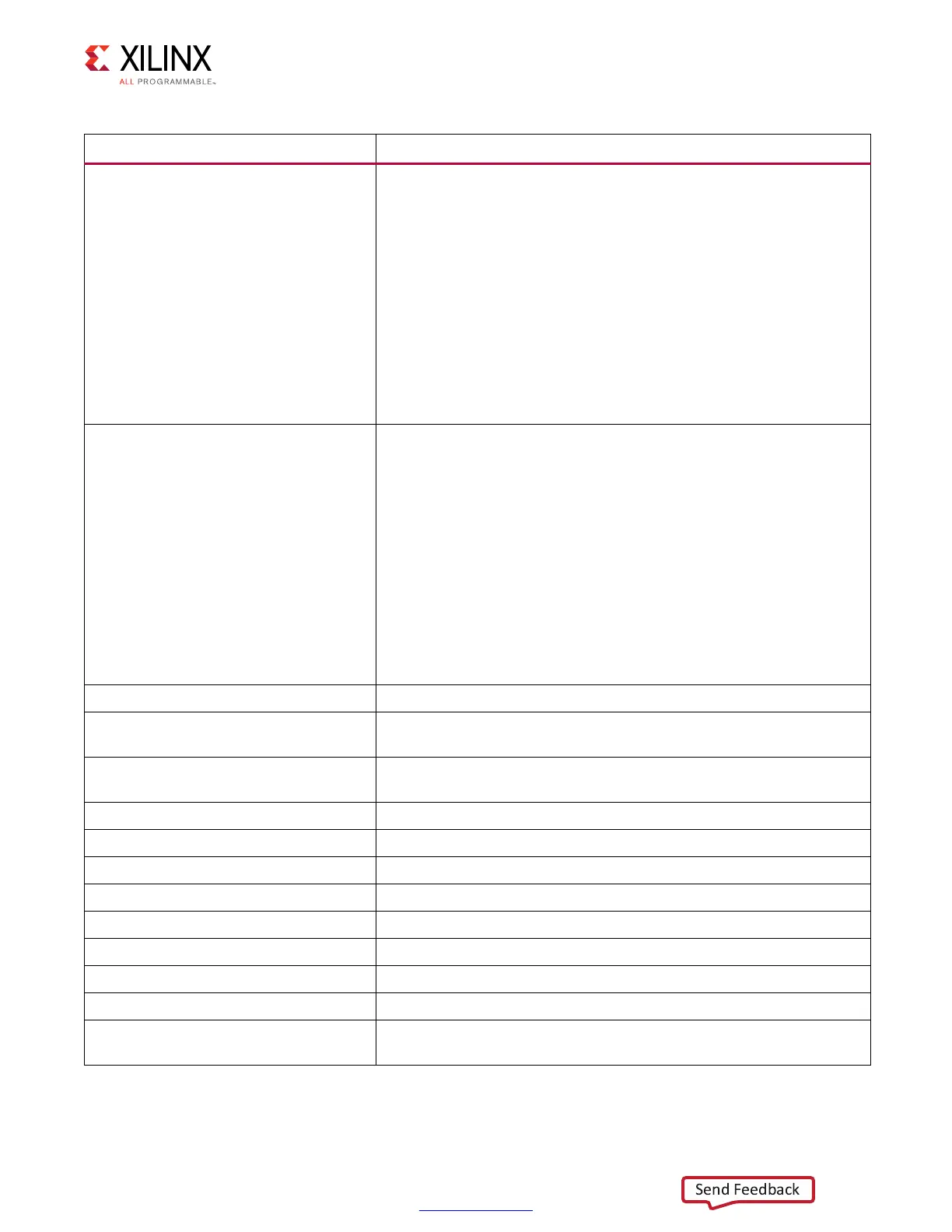
dbg_pi_phase_locked_phy4lanes
Signifies which of the PHASER_IN lanes has achieved lock. It is a 12-bit
bus, three nibble data.
Each nibble corresponds to a bank information. Uppermost Data or
Address/Control byte group selected bank is referred to as Bank0, this
corresponds to nibble 0 or Bits[3:0] of the bus. Numbering of banks is
0, 1, and 2 from top to bottom. Bank1 corresponds to nibble 1 or
Bits[7:4] of the bus. Bank2 corresponds to nibble 2 or Bits[11:8] of the
bus.
LSB to MSB bits in each nibble corresponds to T3 to T0 byte lane
information of the corresponding bank.
For example, Nibble 0, Bit[3] corresponds to T0 byte lane, Bit[2]
corresponds to T1 byte lane, Bit[1] corresponds to T2 byte lane, Bit[0]
corresponds to T3 byte lane information.
dbg_pi_dqs_found_lanes_phy4lanes
Signifies which of the PHASER_IN lanes is able to find the DQS. It is a
12-bit bus, three nibble data.
Each nibble corresponds to a bank information. Uppermost Data or
Address/Control byte group selected bank is referred to as Bank0, this
corresponds to nibble 0 or Bits[3:0] of the bus. Numbering of banks is
0, 1, and 2 from top to bottom. Bank1 corresponds to nibble 1 or
Bits[7:4] of the bus. Bank2 corresponds to nibble 2 or Bits[11:8] of the
bus.
LSB to MSB bits in each nibble corresponds to T3 to T0 byte lane
information of the corresponding bank.
For example, Nibble 0, Bit[3] corresponds to T0 byte lane, Bit[2]
corresponds to T1 byte lane, Bit[1] corresponds to T2 byte lane, Bit[0]
corresponds to T3 byte lane information.
dbg_rd_data_offset Read data offset found during calibration.
dbg_cal1_state_r
State machine variable for MPR and Read Leveling Stage 1. States can
be decoded in the ddr_phy_rdlvl.v module.
dbg_cal1_cnt_cpt_r
Signifies the byte that failed MPR Read Leveling or Read Leveling
Stage 1.
dbg_mux_rd_rise0_r Data pattern received on rising edge 0.
dbg_mux_rd_fall0_r Data pattern received on falling edge 0.
dbg_mux_rd_rise1_r Data pattern received on rising edge 1.
dbg_mux_rd_fall1_r Data pattern received on falling edge 1.
dbg_mux_rd_rise2_r Data pattern received on rising edge 2.
dbg_mux_rd_fall2_r Data pattern received on falling edge 2.
dbg_mux_rd_rise3_r Data pattern received on rising edge 3.
dbg_mux_rd_fall3_r Data pattern received on falling edge 3.
dbg_rdlvl_pat_data_match_r
Asserts when the valid pattern is detected on the data and is found to
match with the expected pattern sent during read leveling.
Table 1-74: DDR2/DDR3 Debug Signals (Cont’d)
Signal Name Description
 Loading...


