Zynq-7000 AP SoC and 7 Series FPGAs MIS v4.1 240
UG586 November 30, 2016
www.xilinx.com
Chapter 1: DDR3 and DDR2 SDRAM Memory Interface Solution
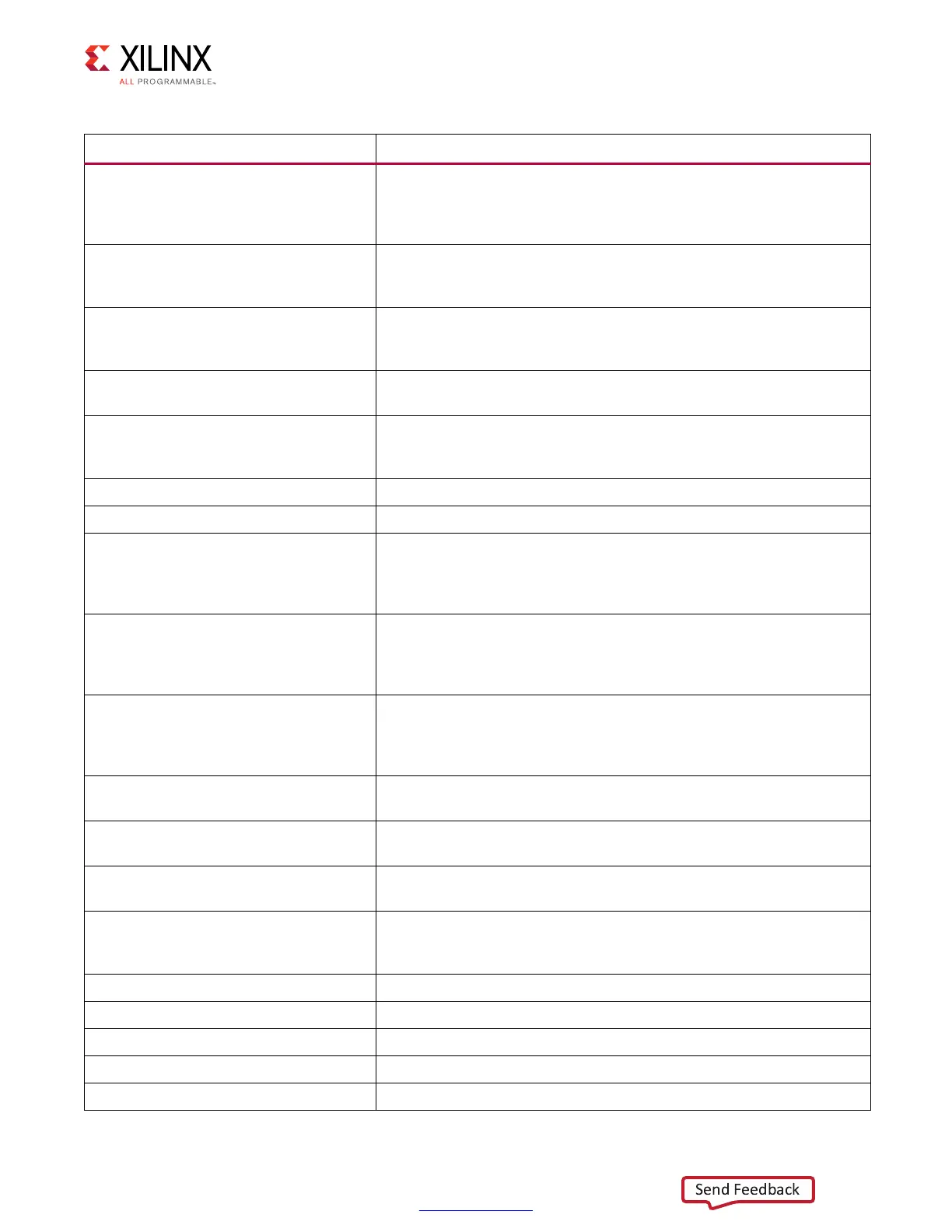
dbg_mux_rd_valid_r
Asserts when the valid pattern is detected on dbg_mux_rd_rise0_r,
dbg_mux_rd_fall0_r, dbg_mux_rd_rise1_r, dbg_mux_rd_fall1_r,
dbg_mux_rd_rise2_r, dbg_mux_rd_fall2_r, dbg_mux_rd_rise3_r, and
dbg_mux_rd_fall3_r.
dbg_cpt_first_edge_cnt_by_dqs
Signifies PHASER_IN fine tap count when the first edge in MPR and
Read Leveling Stage 1 is found. Byte capture based on VIO dbg_dqs
setting.
dbg_cpt_second_edge_cnt_by_dqs
Signifies PHASER_IN fine tap count when then second edge in MPR
and Read Leveling Stage 1 is found. Byte capture based on VIO
dbg_dqs setting.
dbg_cpt_tap_cnt_by_dqs
Signifies the center tap moved to based on when the first and second
edges were found. Byte capture based on VIO dbg_dqs setting.
dbg_dq_idelay_tap_cnt_by_dqs
IDELAY tap value for MPR and Read Leveling Stage 1. This should be
within 2 to 3 taps across all DQS byte groups. Byte capture based on
VIO dbg_dqs setting.
dbg_dbg_calib_rd_data_offset_1 Read data offset found during calibration.
dbg_dbg_calib_rd_data_offset_2 Read data offset found during calibration.
dbg_data_offset
Data Offset used during normal operation. Value changes during
writes, reads, and idle. During writes, it is CWL + 2+slot#. During
non-data commands, it is 0. During reads, it should match what was
found during DQSFOUND calibration (rd_data_offset_ranks).
dbg_data_offset_1
Data Offset used during normal operation. Value changes during
writes, reads, and idle. During writes, it is CWL + 2+slot#. During
non-data commands, it is 0. During reads, it should match what was
found during DQSFOUND calibration (rd_data_offset_ranks).
dbg_data_offset_2
Data Offset used during normal operation. Value changes during
writes, reads, and idle. During writes, it is CWL + 2+slot#. During
non-data commands, it is 0. During reads, it should match what was
found during DQSFOUND calibration (rd_data_offset_ranks).
dbg_cpt_first_edge_cnt
Signifies PHASER_IN fine tap count when the first edge in MPR and
Read Leveling Stage 1 is found.
dbg_cpt_second_edge_cnt
Signifies PHASER_IN fine tap count when then second edge in MPR
and Read Leveling Stage 1 is found.
dbg_cpt_tap_cnt
Center PHASER_IN fine tap value in MPR or Read Leveling Stage 1 is
found.
dbg_dq_idelay_tap_cnt
IDELAY tap value for MPR and Read Leveling Stage 1. This should be
within 2 to 3 taps across all DQS byte groups. Byte capture based on
VIO dbg_dqs setting.
dbg_prbs_rdlvl Debug signals of PRBS Read Level Stage.
dbg_ocal_lim_done Indicates that stage 3 lower and upper limits have been determined.
dbg_ocal_stg3_lim_left Stage 3 lower limit.
dbg_ocal_stg3_lim_right Stage 3 upper limit.
dbg_ocal_center_calib_start OCLKDELAY center calibration start indicator.
Table 1-74: DDR2/DDR3 Debug Signals (Cont’d)
Signal Name Description
 Loading...


