Humphrey Field Analyzer II-
i
series User Manual 2660021145640 A
Custom Testing
12-5
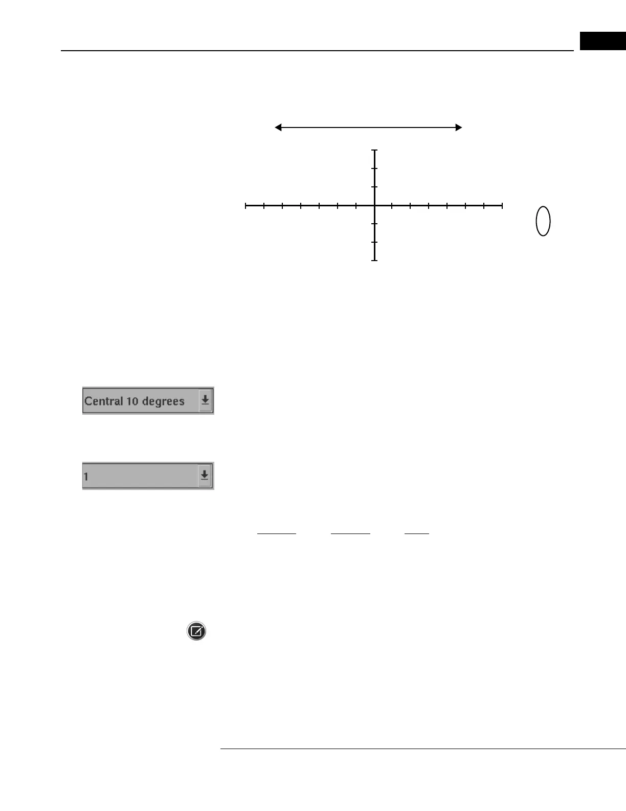
Figure 12.1 is a graph to help explain (X, Y) coordinate systems. For the point shown, X = 5 and Y =
-3. (X, Y) is (5, -3).
Y
X
blind
spot
-3
-2
-1
1
23
4
5
6
7
. . . . . . .
.
. . . .
(5, -3)
1
2
3
-7 -6 -5 -4 -3 -2 -1
(temporal)
(nasal)
Figure 12.1 An Example of the X, Y Coordinate System for the Right Eye
Remember, the Custom test pattern you are designing must be created for the right eye. Therefore,
temporal points will be plotted to the right (positive “X” values) and nasal test points will be to the
left (negative “X” values).
Field Size
This lets you choose one of three field sizes for testing: Cent
ral 10 degrees, Central 30 degrees, or
Full 90 degrees. Each field size is independent of the other two. They may not be combined. The
field size may not be changed once set.
Point Spacing
This option allows you to determine the spacing in degrees betw
een points on the test field. This
point spacing applies to the separation between each point in a Grid as well as the separation of a
Single Point from another Single Point (or Grid point). The point spacing options for each Field Size
are indicated below:
Central 10 Central 30 Full 90
1° * 2° * 6° *
2° 4° 8°
4° 6° 10°
6° 8° 12°
Note: The default point spacings ar
e
marked with asterisks (*).
 Loading...