Humphrey Field Analyzer II-
i
series User Manual 2660021145640 A
Networking Reference
I-3
Connecting Your Network Components
This procedure guides you in interconnecting the HFA II-
i
with your office network.
1 Locate the network connector on the connections panel at the rear of the HFA II-
i
. The panel is
located under a snap-on cover. See Figure 1.9, “Rear View of the HFA II-i with Panel Removed,”
on page 1- 30 . The network connector is located on the panel
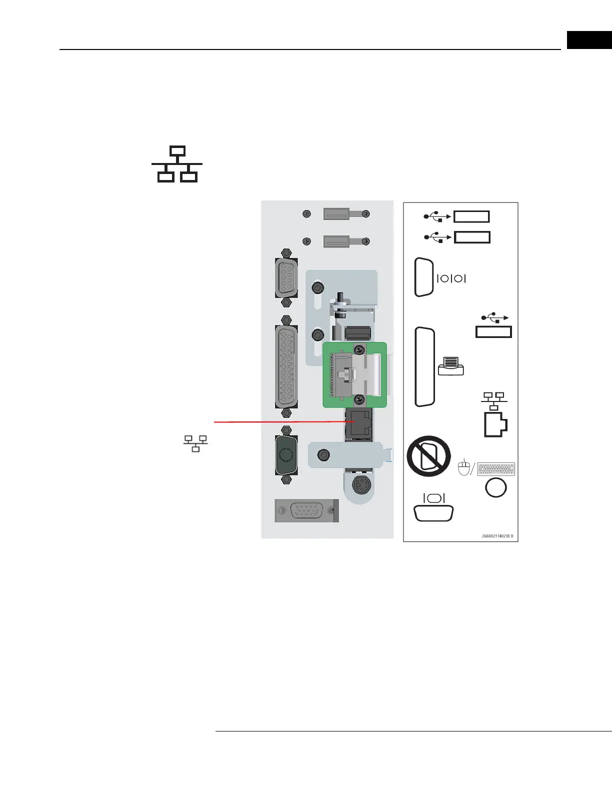
as is shown in Figure I.1. The
connector on the instrument panel is ident
ified with an Ethernet symbol (as shown on the left)
on the label that is attached to the adjoining panel.
Figure I.1 Location of the Network Connector (Panel and Label)
2 Snap one end of the network cable into place in the LAN connector on the HFA back panel.
Note that when you need to remove the cable, you will need to depress the locking tab on the
side of the connector, to free the connector from the socket.
3 Snap the free end of the cable into the network connector of the network router or hub. The
Ethernet (LAN) network connector at that location should look exactly like the one on the back
panel of the HFA II-
i
perimeter.
Network
Connector
 Loading...