Reference Manual ADuCM356
USE CASE CONFIGURATIONS
analog.com Rev. A | 157 of 312
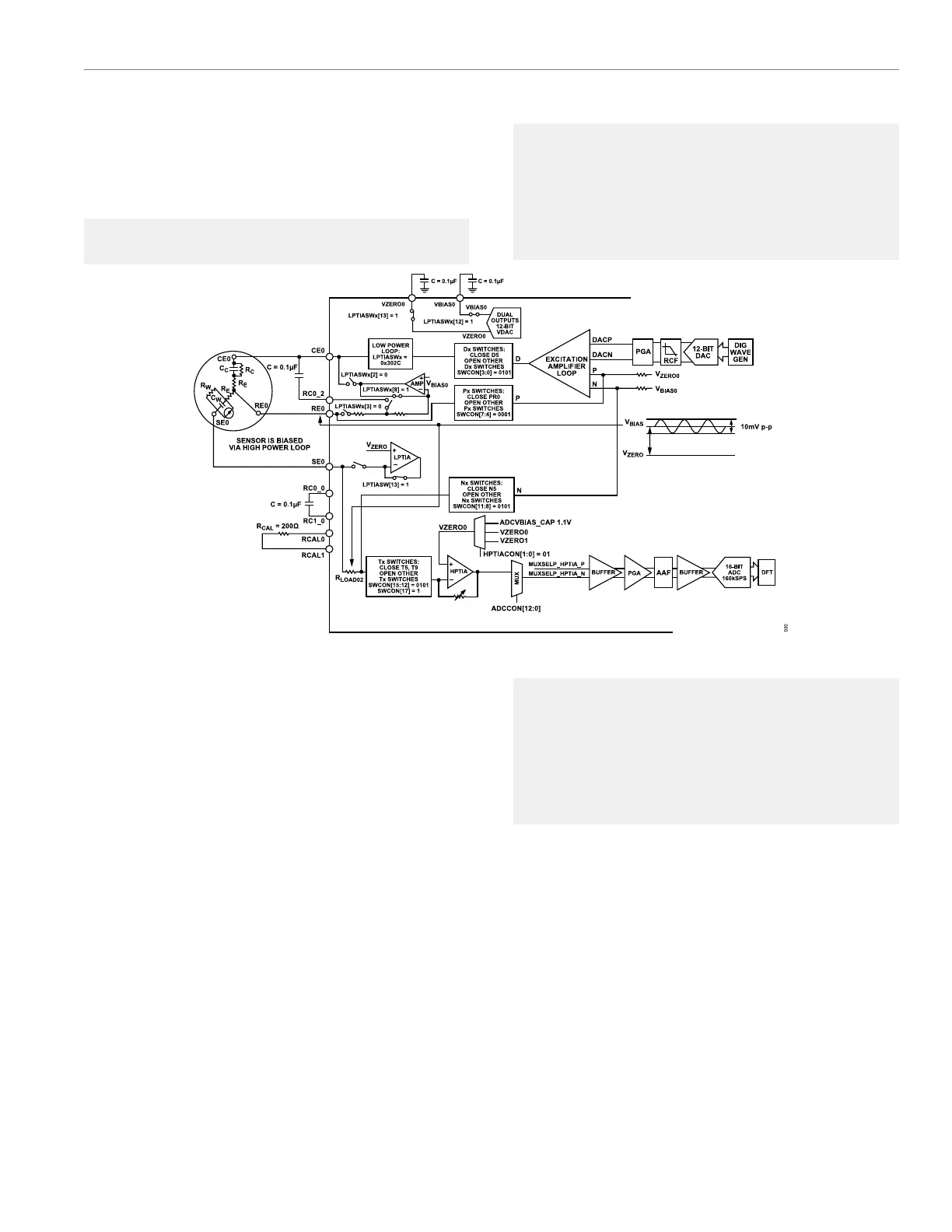
via the high-speed TIA. The ADC signal chain and DFT are used to
calculate the impedance of the R
LOAD02
resistor.
Configure the Tx, Dx, Nx, and Px switches appropriately, as descri-
bed in the following example code:
AfeS►
witchDPNT(SWID_D7_WE0,SWID_P7_WE0,SWID_N5_SE0RL
OAD,SWID_T5_SE0RLOAD|SWID_T9);
// Connect Excitation Amplifier D to the WE
Electrode
// Connect Excitation Amplifier P to SE0
// Connect Excitation Amplifier N to SE0 via
RLOAD02
// Connect HSTIA to SE0 via RLOAD02. Close T9
Figure 42. R
LOAD02
Measurement
Step 4: Measure R
CAL
via the Impedance
Measurement Engine
R
CAL
is a known external fixed resistor, typically 200 Ω, but can be
other values. The electrochemical sensor DC bias voltage is set by
the low-power potentiostat loop.
Configure the Tx, Dx, Nx, and Px switches appropriately, as per the
following example code:
AfeS►
witchDPNT(SWID_D7_WE0,SWID_P7_WE0,SWID_N5_SE0RL
OAD,SWID_T5_SE0RLOAD|SWID_T9);
// Connect Excitation Amplifier D to RCAL0
// Connect Excitation Amplifier P to RCAL0
// Connect Excitation Amplifier N to RCAL1
// Connect HSTIA to RCAL1. Close T9
 Loading...