Reference Manual ADuCM356
USE CASE CONFIGURATIONS
analog.com Rev. A | 158 of 312
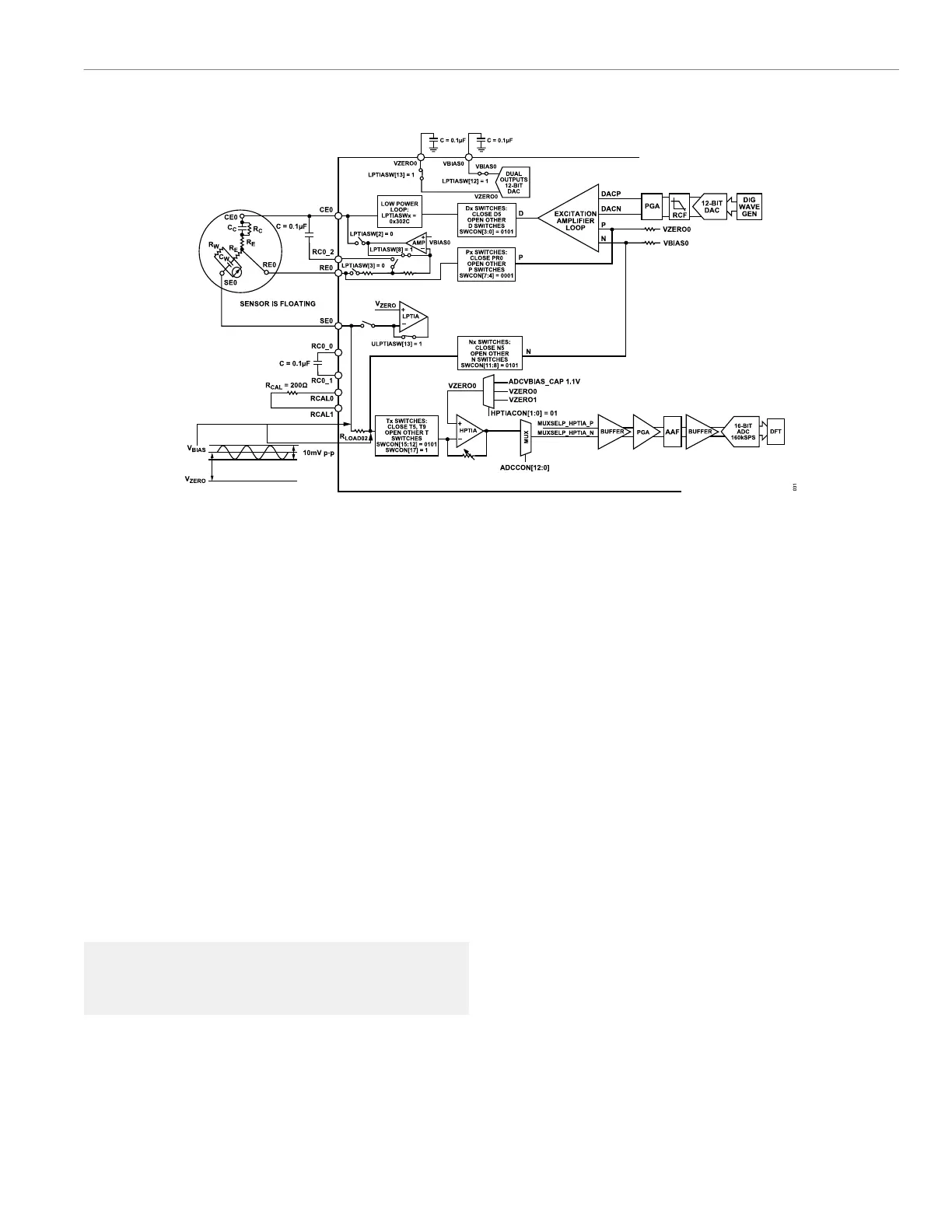
Figure 43. R
CAL
Measurement
The R
CAL
measurement is used to calibrate the R
SENSOR
+ R
LOAD
measurement in Step 3 by using ratiometric measurements. As
shown in Figure 43, the electrochemical sensor is biased via the
low-power potentiostat and low-power TIA amplifiers for Step 4.
The waveform generator and the high-speed DAC generate a 10
mV amplitude sine waveform.
The AC excitation loop D node, P node, and RCAL0 pin are shorted
by setting the Dx switch and Px switch to close the DR0 and PR0
switches (SWCON, Bits[7:0] = 0x11). Other Dx switches and Px
switches are open. The AC excitation loop N node, high-speed TIA
T node, and RCAL1 pin are shorted by setting the Nx switches
and Tx switches to close the NR1 and TR1 switches (SWCON,
Bits[15:8] = 0x85). Close T9 to select R
TIA02
(SWCON Bit 17 =
1). Other Nx switches and Tx switches are open. The stimulus is
added to the 200 Ω R
CAL
and the high-speed TIA. The ADC signal
chain and DFT block are used to calculate the impedance of R
CAL
.
Set the low-power loop switches to allow the excitation amplifier
and the high-speed TIA to set the DC bias voltage level of the
sensor. The following example code demonstrates how to configure
the switches in the low-power loop:
AfeLpTiaSwitchCfg (channel,
SWMODE_AC); //Low Power Loop for AC impe►
dance switch settings (0x3180)
 Loading...