Impianto elettrico
Electric system
sezione / section
P 4
43
A
B
C
D
E
F
G
H
L
M
N
P
749/749 DARK/749S Aggiornamento/Update - M.Y. 2006 - edizione/edition 00
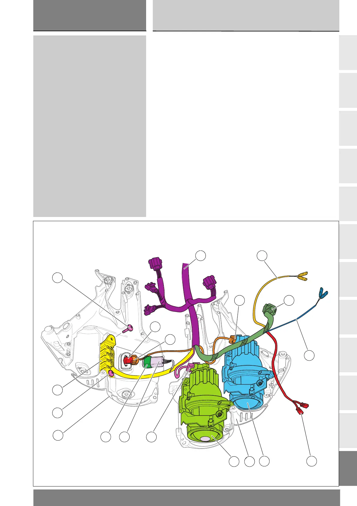
Posizionare il cablaggio anteriore (20)
sul supporto fanale sinistro (9) come
indica la figura.
Inserire il connettore (21), identificato
con la lettera “AB” sul proiettore
abbagliante (19).
Inserire il connettore (22), identificato
con la lettera “AN” sul proiettore
anabbagliante (8).
Posizionare i rami per cablaggio
cruscotto (23), freccia anteriore
sinistra (24), freccia anteriore
destra (25) e luce di posizione (26).
Montare la scatola fusibili (27),
orientandola come in figura, sul
supporto fanale destro (3)
impuntando le viti (28).
Serrare le viti (28) alla coppia
prescritta (Sez. C 3).
Inserire il connettore (29) sul
sensore temperatura aria (30) e
calzare il relè luci (31) nell'apposito
gommino di supporto (32).
Position the front wiring harness (20)
on the LH headlight support (9) as
shown in the figure.
Insert the connector (21) marked AB
to the high beam headlight (19).
Insert the connector (22) marked AN
to the low beam headlight (8).
Position the wiring for the instrument
panel (23), front left turn indicator (24),
front right turn indicator (25) and
parking light (26).
Install the fusebox (27), positioning it as
shown in the figure, to the RH headlight
support (3) and start the screws (28).
Tighten the screws (28) to the
specified torque (Sect. C 3).
Fit connector (29) to the air temperature
sensor (30) and fit the lights relay (31)
into its rubber support (32).
0
8
19
25
30
24
27
28
3
29
32 31
22
9
26
24
28
20
21