A
B
C
D
E
F
G
H
L
M
N
P
Impianto elettrico
Electric system
sezione / section
P 4
44 749/749 DARK/749S Aggiornamento/Update - M.Y. 2006 - edizione/edition 00
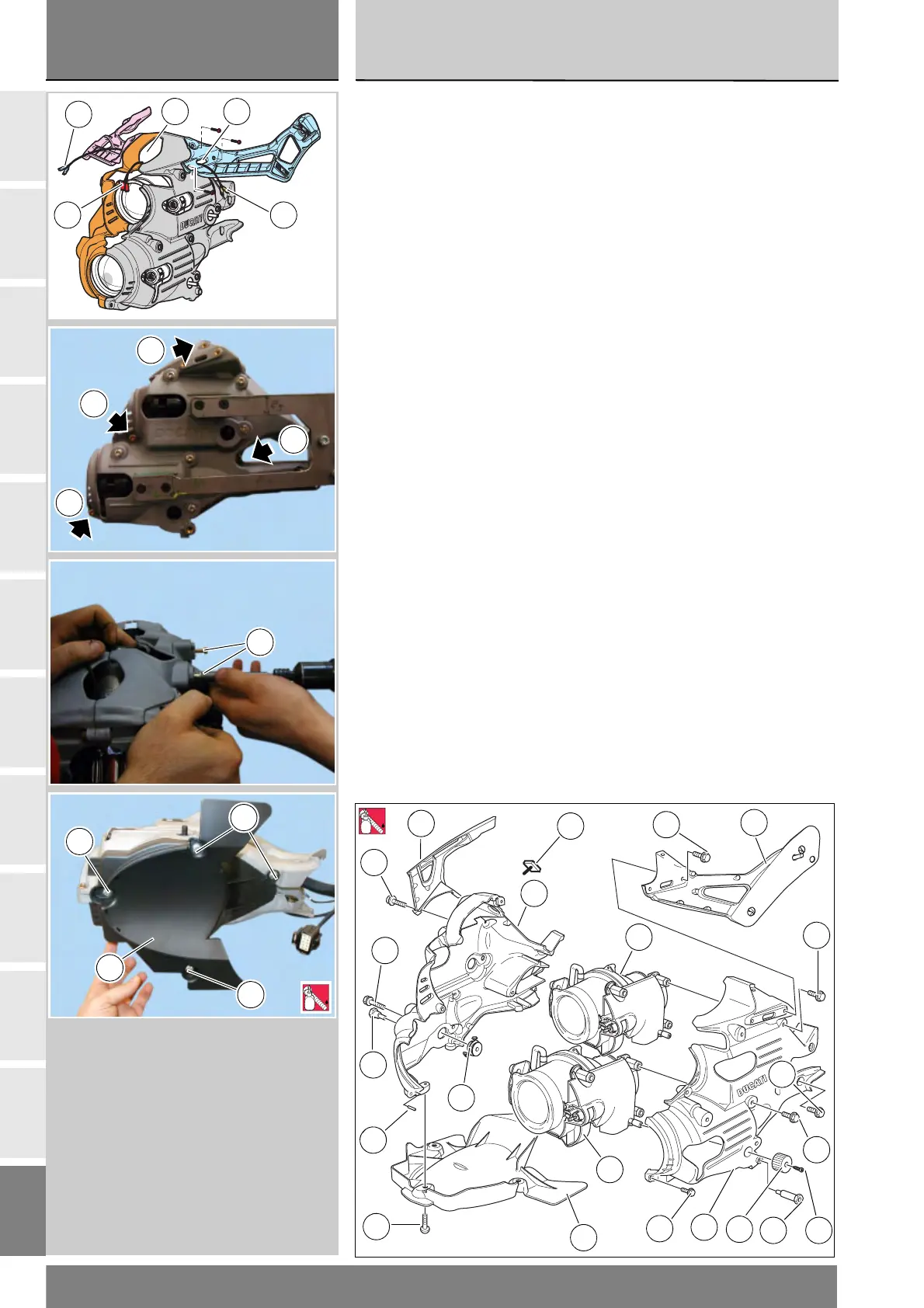
Montare il supporto fanale destro (3)
sul supporto fanale sinistro (9)
centrando i due particolari sulle
spine (10) e facendo attenzione a
non schiacciare i rami del cablaggio.
Prima di unire le due parti fare passare
nelle apposite asole (A) i due cavi delle
frecce anteriori (24) e (25) ed il cavo per
la luce di posizione (26) nell'asola (B).
Fissare i supporti fanale impuntando
le viti (18) e serrarle alla coppia
presritta (Sez. C 3).
Fissare con le viti (4) dalla parte
esterna del supporto fanale destro i
proiettori e serrare le viti alla coppia
prescritta (Sez. C 3).
Montare il paraspruzzi (7) impuntando
le viti (6) dopo avergli applicato
frenafiletti prescritto e serrarle alla
coppia prescritta (Sez. C 3) prima le
due sui fori poi le due sulle asole.
Fissare i pomelli (11) ai proiettori
impuntando le viti (17) e serrandole
alla coppia prescritta (Sez. C 3).
Se sono state rimosse le
colonnette (13) e (16) montarle
applicando frenafiletti prescritto.
19
1
2
4
5
3
13
10
6
7
8
18
16
11
9
17
4
12
4
2
14
19
2
LOCK
Fit the RH headlight support (3) to
the LH headlight support (9) making
sure the two parts are aligned with
their lugs (10) and making sure not
to pinch the cabling.
Before securing the two halves
together, pass the wires of the two
front turn indicator (24) and (25)
through slots (A) and the parking
light cable (26) through slot (B).
Insert the retaining screws (18)
and tighten to the specified torque
(Sect. C 3).
Secure the headlights with the
screws (4) from the exterior of the RH
headlight support and tighten to the
specified torque (Sect. C 3).
Fit the splash guard (7), insert the
screws (6) (use the recommended
threadlocker) and tighten to the
specified torque (Sect. C 3),
tightening first the two screws in
the round holes and then the two
screws in the slots.
Fix the knobs (11) to the headlights
with screws (17) and tighten them to
the specified torque (Sect. C 3).
If the studs (13) and (16) have been
removed, install them with the
specified threadlocker.
B A
24
25
26
18
18
18
18
4
6
6
6
7
2
LOCK