2 - 97
Chapter 2 Troubleshooting
FIP-1.58 042-372 / 042-373: IOT K Mode Solenoid Error 1/2
Step Check
Remedy
Yes No
Possible causative parts:
DRIVE ASSY PH (PL7.1.4)
PWBA MCU (PL8.3.6)
HARNESS ASSY KSNR REGCL MG AIO (PL9.1.9)
1
Does the error still occur when the power is turned OFF and
ON?
Go to step 2. End of work.
2
Checking the K Mode Solenoid (Color Mode Switching
Solenoid) for operation.
Does the K Mode Solenoid function normally?
Checked by [Digital Output] - [K Mode Solenoid] in [IOT
Diag] of diagnosis.
During this check, close the COVER ASSY FRONT.
Does the K Mode Solenoid click sound arise from the
DRIVE ASSY PH, when the K Mode Solenoid check is
performed?
Go to step 3. Go to step 4.
3
Checking after resetting the DRIVE ASSY PH.
Reseat the DRIVE ASSY PH.
Does the error still occur when the power is turned OFF and
ON?
Go to step 8. End of work.
4
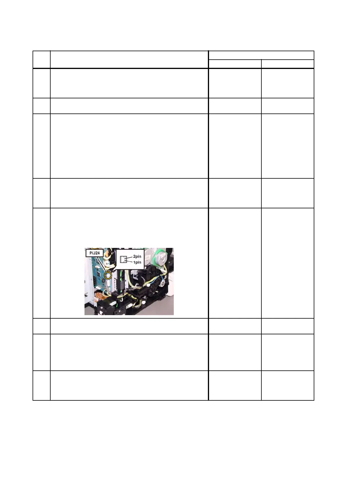
Checking the connector of the K Mode Solenoid in the
DRIVE ASSY PH for connection.
Check the connection between the PWBA MCU and K
Mode Solenoid.
Is P/J24 connected correctly?
Go to step 6.
Reconnect the
connector P/J24
correctly, then go
to step 5.
5
Does the error still occur when the power is turned OFF and
ON?
Go to step 6. End of work.
6
Checking the power to the K Mode Solenoid.
Disconnect J24 from the PWBA MCU.
Is the voltage across P24-1pin <=> ground on the PWBA
MCU, about +24 VDC when the Interlock Switch (HARN
ASSY INTERLOCK AIO) is pushed?
Go to step 7.
Replace the KIT
PWBA MCU.
(Refer to
REP8.10.)
7
Checking the K Mode Solenoid for resistance.
Disconnect P/J24 from the PWBA MCU.
Is the resistance across J24-1 and J24-2 about 80 to 110-
ohm?
Replace the KIT
PWBA MCU.
(Refer to
REP8.10.)
Replace the KIT
DRIVE ASSY PH.
(Refer to REP7.3.)
 Loading...