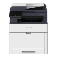
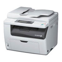
4 - 164
Chapter 4 Disassembly / Assembly and Adjustments
REP5.4 HOLDER ASSY TCRU (K), (C), (M), (Y) (PL5.1.17~20)
[Removal]
1) Remove the CASSETTE ASSY 250 MG AIO. (REP2.1)
2) Open the COVER ASSY FRONT (PL1.2.1).
Cover the drum of the PHD ASSY to avoid exposure to light.
3) Remove the PHD ASSY. (REP4.6)
The FUSING UNIT part is very hot. Take added care not to get burned when
performing the service operation.
4) Remove the FUSING UNIT. (REP6.1)
5) Remove the COVER ASSY SIDE R AIO. (REP1.8)
6) Remove the COVER ASSY SIDE L AIO. (REP1.9)
7) Remove the COVER POLE OUT AIO. (REP1.1)
8) Remove the SHIELD ASSY ESS AIO. (REP8.5)
9) Remove the COVER POLE IN AIO. (REP1.3)
10) Remove the COVER SCANNER LOW AIO. (REP1.2)
11) Remove the COVER REAR AIO. (REP1.5)
12) Remove the COVER TOP AIO. (REP1.4)
13) Remove the CHASSIS ASSY LVPS. (REP8.12)
14) Remove the HARNESS ASSY FRONT USB (PL10.1.13) and BRACKET ASSY USB
(PL10.1.14). (REP9.6)
15) Remove the TRAY ASSY. (REP9.3)
16) Remove the ADF ASSY. (REP9.1)
17) Remove the IIT ASSY SUB. (REP10.5)
18) Remove the PLATE ASSY TOP. (REP8.7)
19) Remove the CHASSIS ASSY INLET. (REP8.13)
20) Remove the TONER CARTRIDGE (K), (C), (M), (Y). (REP5.5)
Described below is the removal procedure common among the four HOLDER
ASSY TCRU.

 Loading...