7 - 14
Chapter 7 Wiring Data
7.5 Interconnection Wiring Diagram of Parts
7.5.1 Notes on Using the Wiring Diagram between Parts
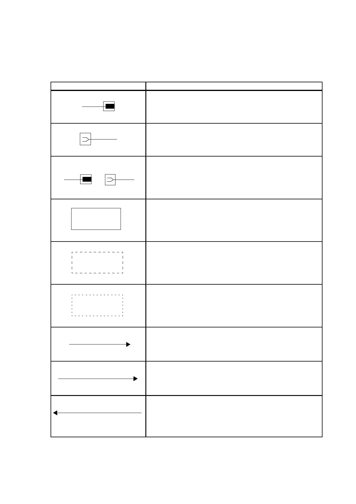
The following describes the legend of the wiring diagrams between parts shown on the following pages.
Symbols Description
Denotes a plug.
Denotes a jack.
Denotes Pin yy and Jack yy of the connector Pxx and Jxx.
Denotes the parts.
PL X.Y.Z implies the item "Z" of plate (PL) "X.Y" in Chapter 5.
Parts List.
Denotes functional parts attached with functional parts name.
Denotes the control and its outline in PWB.
Denotes a connection between parts with harnesses or wires,
attached with signal name/contents.
Denotes the function, and logic value of the signal to operate the
function (Low: L, High: H).
The given voltage is for signal in high status.
The arrow indicates the direction of signal.
Denotes the function, and logic value of the signal when the func-
tion operated (Low: L, High: H).
The given voltage is for signal in high status.
The arrow indicates the direction of signal.
EXIT PAPER SENSED(L)+3.3VDC

 Loading...