2 - 106
Chapter 2 Troubleshooting
18
Checking the Regi. Sensor (SENSOR PHOTO) for
operation.
Does the number on the screen increase by one, when the
actuator (ACTUATOR REGI IN) is operated?
Remove the CHUTE ASSY LOW (PL3.2.27) once to check
the operation.
Checked by [Digital Input] - [Regi Sensor] in [IOT Diag] of
diagnosis.
Replace the KIT
PWBA MCU.
(Refer to
REP8.10.)
Go to step 26.
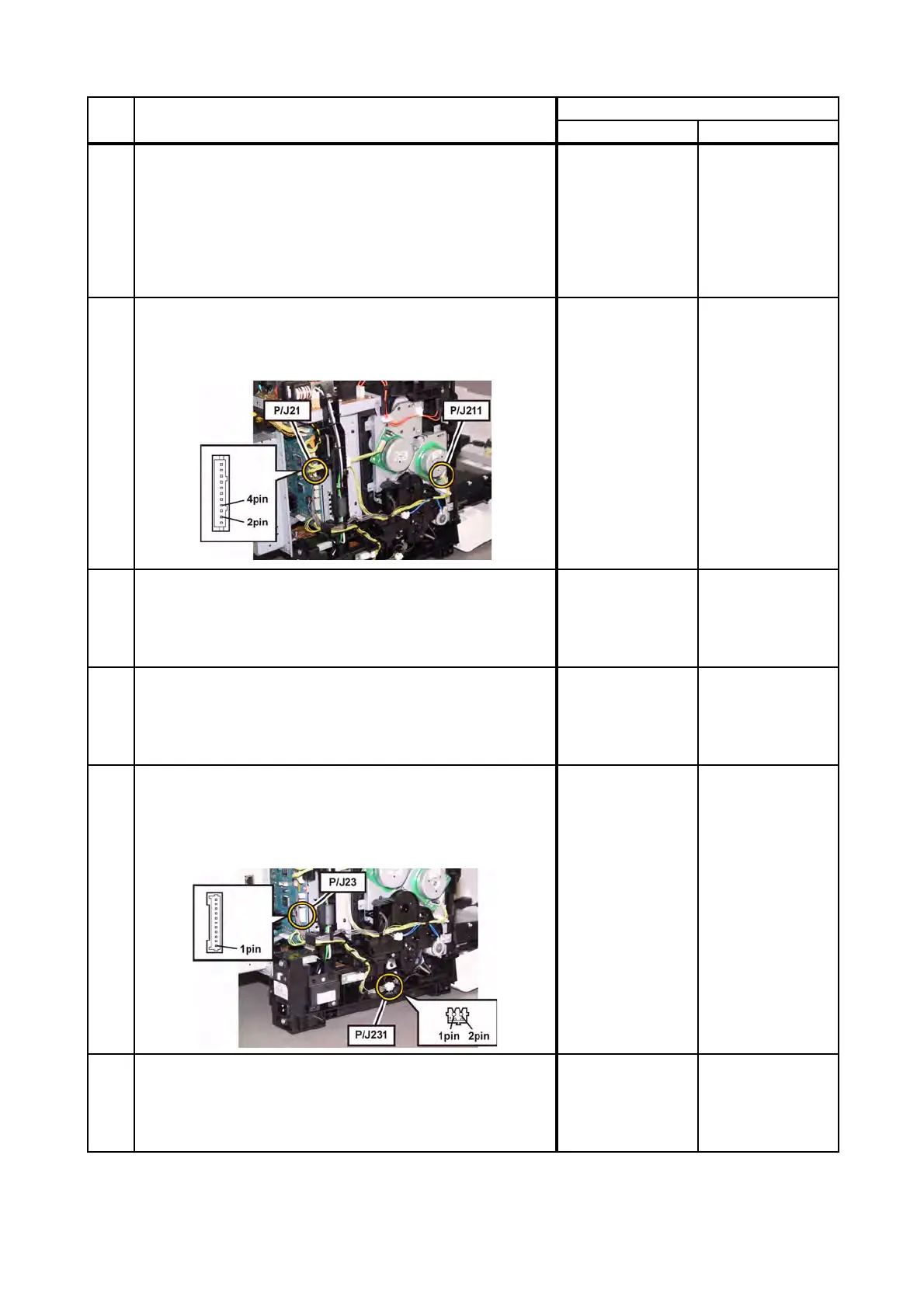
19
Checking the connectors for connection.
Check the connections between the PWBA MCU and
DRIVE ASSY MAIN (Main Motor).
Are P/J21 and P/J211 connected correctly?
Go to step 20.
Reconnect the
connector(s) P/
J21 and/or P/J211
correctly.
20
Checking the HARNESS ASSY MAIN MOT MG AIO for
continuity.
Disconnect J21 from the PWBA MCU.
Disconnect J211 from the DRIVE ASSY MAIN.
Is each cable of J21 <=> J211 continuous?
Go to step 21.
Replace the
HARNESS ASSY
MAIN MOT MG
AIO.
21
Checking the power to the DRIVE ASSY MAIN.
Disconnect J21 from the PWBA MCU.
Are the voltages across J21-2pin/J21-4pin <=> ground on
the PWBA MCU, about +24 VDC when the interlock switch
(HARN ASSY INTERLOCK AIO) is pushed?
Replace the KIT
DRIVE ASSY
MAIN. (Refer to
REP7.2.)
Replace the KIT
PWBA MCU.
(Refer to
REP8.10.)
22
Checking the connectors of the Tray 1 Feed Solenoid
(SOLENOID FEED MSI) for connection.
Check the connections between the PWBA MCU and
SOLENOID FEED MSI.
Are P/J23 and P/J231 connected correctly?
Go to step 23.
Reconnect the
connector(s) P/
J23 and/or P/J231
correctly.
23
Checking the HARNESS ASSY L SIDE MG AIO for
continuity.
Disconnect J23 from the PWBA MCU.
Disconnect P231 from the SOLENOID FEED MSI.
Is each cable of J23 <=> P231 continuous?
Go to step 24.
Replace the
HARNESS ASSY
L SIDE MG AIO.
Step Check
Remedy
Yes No
 Loading...