2 - 115
Chapter 2 Troubleshooting
23
Checking the HARNESS ASSY L SIDE MG AIO for
continuity.
Disconnect J23 from the PWBA MCU.
Disconnect P231 from the SOLENOID FEED MSI.
Is each cable of J23 <=> P231 continuous?
Go to step 24.
Replace the
HARNESS ASSY
L SIDE MG AIO.
24
Checking the power to the SOLENOID FEED MSI.
Disconnect J23 from the PWBA MCU.
Is the voltage across P23-1pin <=> ground on the PWBA
MCU, about +24 VDC when the Interlock Switch (HARN
ASSY INTERLOCK AIO) is pushed?
Go to step 25.
Replace the KIT
PWBA MCU.
(Refer to
REP8.10.)
25
Checking the SOLENOID FEED MSI for resistance.
Disconnect P/J231 of the SOLENOID FEED MSI.
Is the resistance across J231-1 and J231-2 about 96 ohm?
Replace the KIT
PWBA MCU.
(Refer to
REP8.10.)
Replace KIT
FEED ROLL/SOL/
CLUTCH. (Refer
to REP3.2.)
26
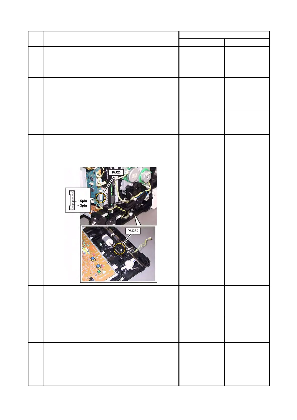
Checking the connectors of the SENSOR PHOTO (REGI
SENSOR) for connection.
Check the connections between the PWBA MCU and
SENSOR PHOTO.
Are P/J23 and P/J232 connected correctly?
Go to step 27.
Reconnect the
connector(s) P/
J23 and/or P/J232
correctly.
27
Checking the HARNESS ASSY L SIDE MG AIO for
continuity.
Disconnect J23 from the PWBA MCU.
Disconnect J232 from the SENSOR PHOTO.
Is each cable of J23 <=> J232 continuous?
Go to step 28.
Replace the
HARNESS ASSY
L SIDE MG AIO.
28
Checking the power to the SENSOR PHOTO.
Disconnect J23 from the PWBA MCU.
Is the voltage across P23-3pin <=> ground on the PWBA
MCU, about +3.3 VDC?
Go to step 29.
Replace the KIT
PWBA MCU.
(Refer to
REP8.10.)
29
Checking the SENSOR PHOTO for operation.
Check the voltage across J23-5pin <=> ground on the
PWBA MCU.
Remove the CHUTE ASSY LOW (PL3.2.27) once to check
the operation.
Does the voltage change, when the actuator (ACTUATOR
REGI IN) is operated?
Replace the KIT
PWBA MCU.
(Refer to
REP8.10.)
Replace the
SENSOR
PHOTO:REGI.
(Refer to REP3.7.)
Step Check
Remedy
Yes No

 Loading...