2 - 140
Chapter 2 Troubleshooting
11
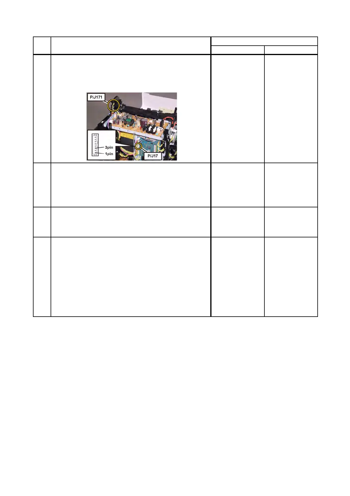
Checking the connectors of the Exit Sensor in the FUSING
UNIT for connection.
Check the connections between the PWBA MCU and
FUSING UNIT.
Are P/J17 and P/J171 connected correctly?
Go to step 12.
Reconnect the
connector(s) P/
J17 and/or P/J171
correctly.
12
Checking the HARNESS ASSY FUSING UNIT MG AIO for
continuity.
Remove the FUSING UNIT.
Disconnect J17 from the PWBA MCU.
Is each cable of J17 <=> P171 continuous?
NOTE: P171 is attached to the frame.
Go to step 13.
Replace the
HARNESS ASSY
FUSING UNIT MG
AIO.
13
Checking the power to the Exit Sensor in the FUSING UNIT.
Disconnect the connector of J17 on the PWBA MCU.
Is the voltage across J17-1pin <=> ground on the PWBA
MCU, about +3.3 VDC?
Go to step 14.
Replace the KIT
PWBA MCU.
(Refer to
REP8.10.)
14
Checking the Exit Sensor for operation.
Check the voltage across J17-3pin <=> ground on the
PWBA MCU.
Does the voltage change, when the actuator of the Exit
Sensor is operated?
Replace the KIT
PWBA MCU.
(Refer to
REP8.10.)
Warning: Start the
operation after the
FUSING UNIT has
cooled down.
Replace the
FUSING UNIT.
(Refer to REP6.1.)
After replacement,
be sure to clear
the life counter
value.
Step Check
Remedy
Yes No
 Loading...