4 - 249
Chapter 4 Disassembly / Assembly and Adjustments
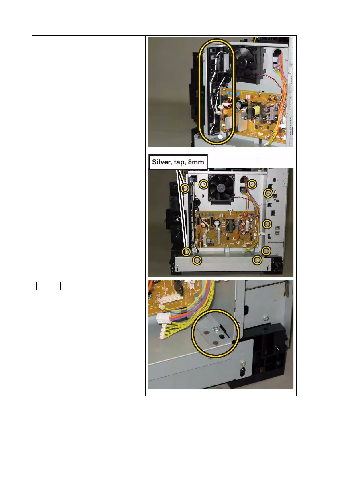
13) Release the harness of the HAR-
NESS ASSY FUSING UNIT MG
AIO (PL6.1.2) and harness of the
SWITCH ASSY INLET MG AIO
(PL8.3.7) from the GUIDE HAR-
NESS LVPS (PL8.2.11).
14) Remove the seven screws (silver,
M4, 6mm) and the two screws (sil-
ver, tap, 8mm) that fix the CHAS-
SIS LVPS to the printer.
When carrying out the work
described next procedure,
lift the CHASSIS LVPS
slightly up, because the
notch of the CHASSIS
LVPS hits the screw.
 Loading...