Operation Manual – ACL
H3C S3100 Series Ethernet Switches Chapter 1 ACL Configuration
1-17
[Sysname-acl-adv-3000] rule 1 deny ip destination 192.168.1.2 0 time-range
test
[Sysname-acl-adv-3000] quit
# Apply ACL 3000 on Ethernet 1/0/1.
[Sysname] interface Ethernet1/0/1
[Sysname-Ethernet1/0/1] packet-filter inbound ip-group 3000
1.6.3 Layer 2 ACL Configuration Example
I. Network requirements
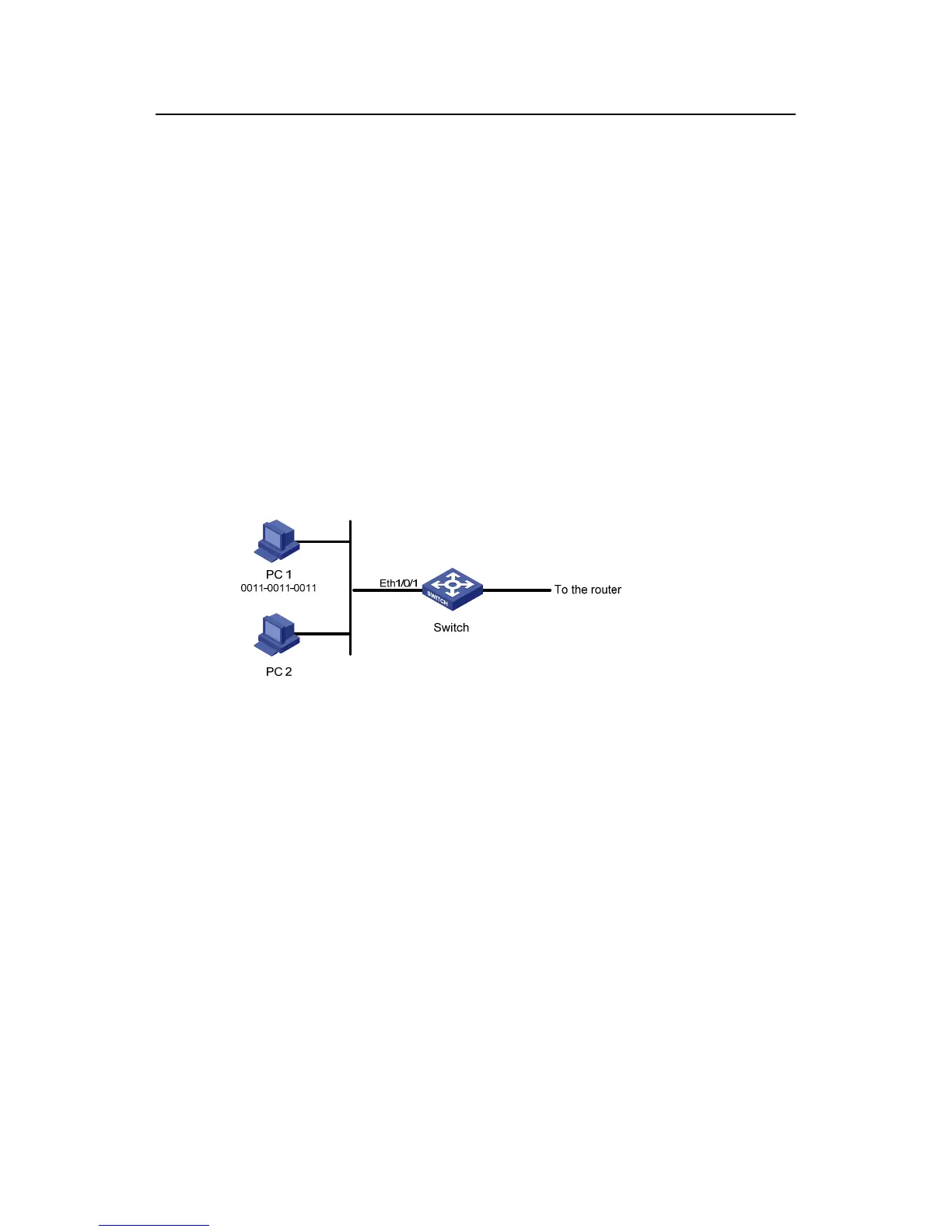
PC 1 and PC 2 connect to the switch through Ethernet 1/0/1. PC1’s MAC address is
0011-0011-0011. Apply an ACL to filter packets with the source MAC address of
0011-0011-0011 and the destination MAC address of 0011-0011-0012 from 8:00 to
18:00 everyday.
II. Network diagram
Figure 1-5 Network diagram for Layer 2 ACL
III. Configuration procedure
# Define a periodic time range that is active from 8:00 to 18:00 everyday.
<Sysname> system-view
[Sysname] time-range test 8:00 to 18:00 daily
# Define ACL 4000 to filter packets with the source MAC address of 0011-0011-0011
and the destination MAC address of 0011-0011-0012.
[Sysname] acl number 4000
[Sysname-acl-ethernetframe-4000] rule 1 deny source 0011-0011-0011
ffff-ffff-ffff dest 0011-0011-0012 ffff-ffff-ffff time-range test
[Sysname-acl-ethernetframe-4000] quit
# Apply ACL 4000 on Ethernet 1/0/1.
[Sysname] interface Ethernet1/0/1
[Sysname-Ethernet1/0/1] packet-filter inbound link-group 4000

 Loading...


