Operation Manual – NTP
H3C S3100 Series Ethernet Switches Chapter 1 NTP Configuration
1-19
The above output information indicates that Device B is synchronized to Device A, and
the stratum level of its clock is 3, one level lower than that of Device A.
# View the information about NTP sessions of Device B. (You can see that Device B
establishes a connection with Device A.)
[DeviceB] display ntp-service sessions
source reference stra reach poll now offset delay disper
**************************************************************************
[12345]1.0.1.11 127.127.1.0 2 1 64 1 350.1 15.1 0.0
note: 1 source(master),2 source(peer),3 selected,4 candidate,5 configured
Total associations : 1
1.8.2 Configuring NTP Symmetric Peer Mode
I. Network requirements
z The local clock of Device A is set as the NTP master clock, with the clock stratum
level of 2.
z Device C (an S3100 Ethernet switch) uses Device A as the NTP server, and
Device A works in server mode automatically.
z The local clock of Device B is set as the NTP master clock, with the clock stratum
level of 1. Set Device C as the peer of Device B.
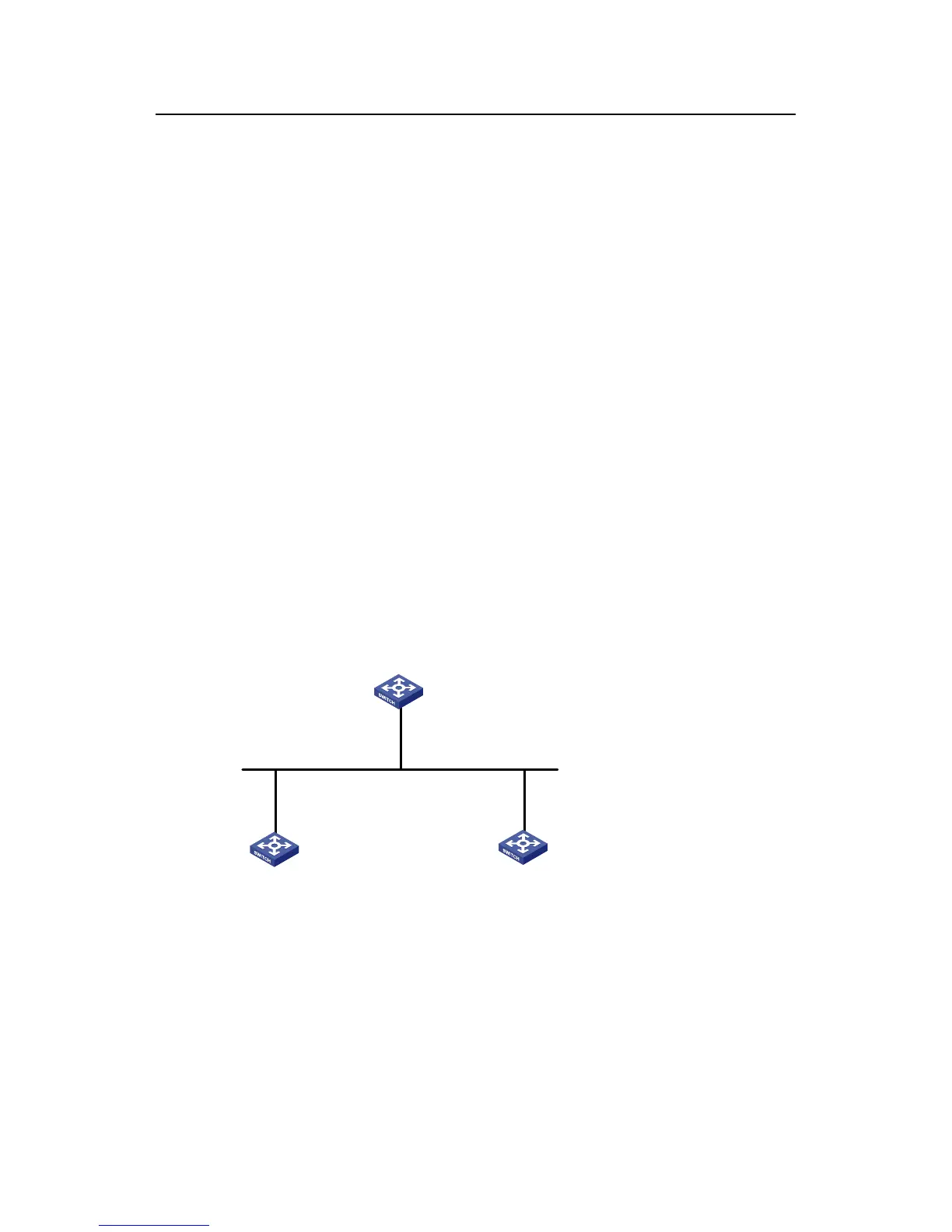
II. Network diagram
Device A
Device B Device C
3.0.1.31/24
3.0.1.32/24 3.0.1.33/24
Figure 1-7 Network diagram for NTP peer mode configuration
III. Configuration procedure
1) Configure Device C.
# Set Device A as the NTP server.
<DeviceC> system-view
[DeviceC] ntp-service unicast-server 3.0.1.31
2) Configure Device B (after the Device C is synchronized to Device A).

 Loading...


