Operation Manual – Smart Link-Monitor Link
H3C S3100 Series Ethernet Switches Chapter 2 Monitor Link Configuration
2-2
2.1.1 How Monitor Link Works
BLOCK
Switch A Switch B
Eth1/0/1
Eth1/0/2
Switch C Switch D
Switch E
Eth1/0/1
Eth1/0/2
Eth1/0/3
Eth1/0/1
Eth1/0/2
Eth1/0/11
Eth1/0/12
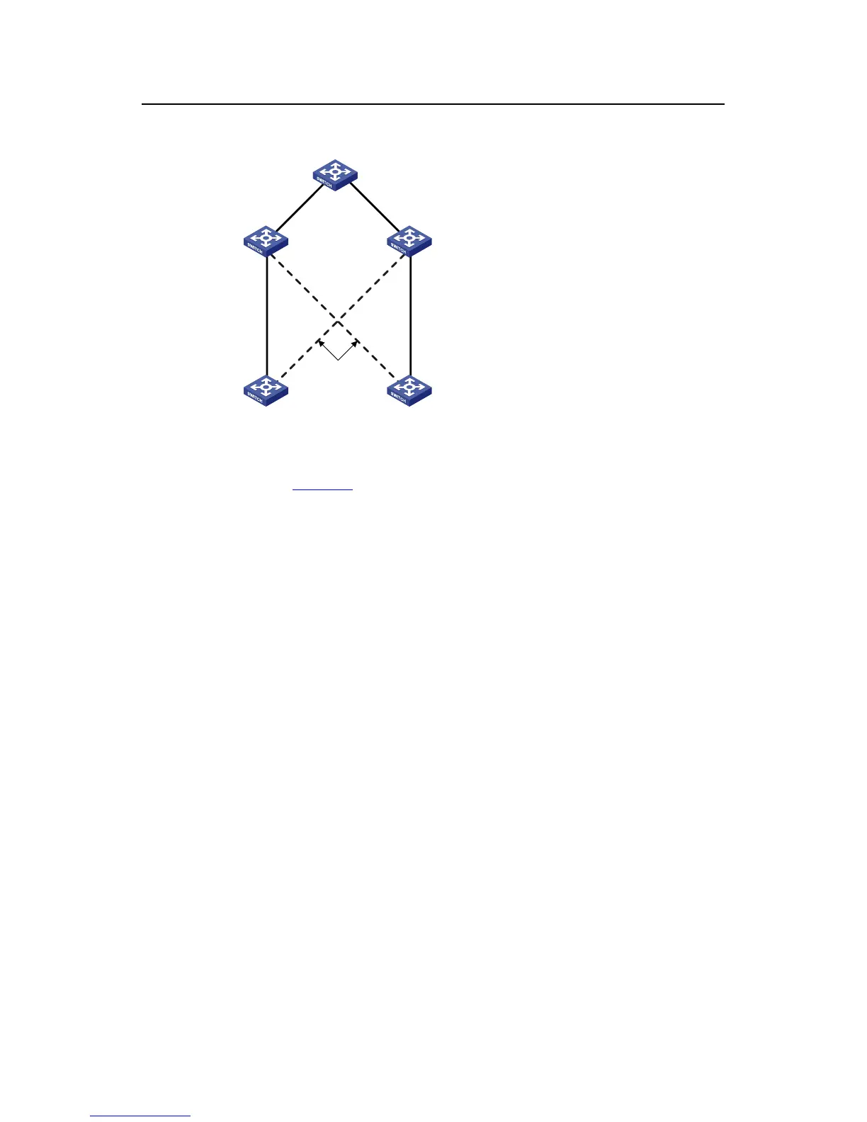
Figure 2-2 Network diagram for a Monitor Link group implementation
As shown in
Figure 2-2, the devices Switch C and Switch D are connected to the uplink
device Switch E. Switch C is configured with a Monitor Link group, where Ethernet1/0/1
is the uplink port, while Ethernet1/0/2 and Ethernet1/0/3 are the downlink ports. Switch
A is configured with a Smart Link group, where Ethernet1/0/1 is the master port and
Ethernet1/0/2 is the slave port.
z If Switch C is not configured with Monitor Link group, when the link for the uplink
port Ethernet1/0/1 on Switch C fails, the links in the Smart Link group are not
switched because the link for the master port Ethernet1/0/1 of Switch A configured
with Smart Link group operates normally. Actually, however, the traffic on Switch A
cannot be up-linked to Switch E through the link of Ethernet1/0/1.
z If Switch C is configured with Monitor Link group and Monitor Link group detects
that the link for the uplink port Ethernet1/0/1 fails, all the downlink ports in the
group are shut down; therefore, Ethernet1/0/3 on Switch C is blocked. Now, Smart
Link group configured on Switch A detects that a link fault occurs on the master
port Ethernet1/0/1. Then, Smart Link immediately activates the slave port
Ethernet1/0/2 so that traffic is switched to the backup link.

 Loading...


