Operation Manual – Smart Link-Monitor Link
H3C S3100 Series Ethernet Switches Chapter 1 Smart Link Configuration
1-3
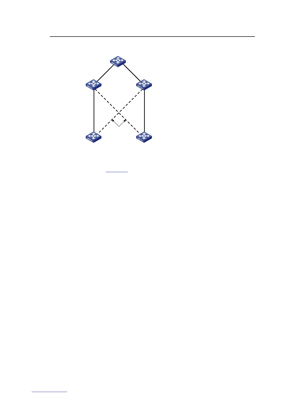
1.1.2 Operating Mechanism of Smart Link
BLOCK
Switch A Switch B
Eth1/0/1
Eth1/0/2
Switch C Switch D
Switch E
Eth1/0/1
Eth1/0/2
Eth1/0/3
Eth1/0/1
Eth1/0/2
Eth1/0/11
Eth1/0/12
Figure 1-2 Network diagram of Smart Link operating mechanism
As shown in
Figure 1-2, Ethernet1/0/1 on Switch A is active and Ethernet1/0/2 on
Switch A is blocked. When the link connected to Ethernet1/0/1 fails, Ethernet1/0/1 is
blocked automatically, and the state of Ethernet1/0/2 turns to active state.
z When link switching occurs in the Smart Link group, MAC forwarding entries and
ARP entries of each device in the network may be out of date. In order to
guarantee correct packet transmission, you must enable the Smart Link device to
send flush messages to notify the other devices in the network to refresh their own
MAC forwarding entries and ARP entries. In this case, all the uplink devices must
be capable of identifying flush messages from the Smart Link group and refreshing
MAC forwarding entries and ARP entries.
z On a Smart Link–enabled device, if a port is blocked due to link failure, the port
remains blocked after the link recovers from the failure, and does not preempt the
traffic resource. Therefore, the traffic stays stable. The port does not come into the
forwarding state until the next link switching.

 Loading...


