Operation Manual – QoS-QoS Profile
H3C S3100 Series Ethernet Switches Chapter 1 QoS Configuration
1-7
802.1p priority lies in Layer 2 packet headers and is applicable to occasions where the
Layer 3 packet header does not need analysis but QoS must be assured at Layer 2.
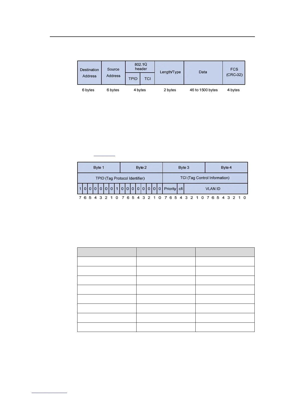
Figure 1-3 An Ethernet frame with an 802.1Q tag header
As shown in the figure above, each host supporting 802.1Q protocol adds a 4-byte
802.1Q tag header after the source address of the former Ethernet frame header when
sending packets.
The 4-byte 802.1Q tag header consists of the tag protocol identifier (TPID, two bytes in
length), whose value is 0x8100, and the tag control information (TCI, two bytes in
length).
Figure 1-4 describes the detailed contents of an 802.1Q tag header.
Figure 1-4 802.1Q tag headers
In the figure above, the priority field (three bits in length) in TCI is 802.1p priority (also
known as CoS precedence), which ranges from 0 to 7.
Table 1-4 Description on 802.1p priority
802.1p priority (decimal) 802.1p priority (binary) Description
0 000 best-effort
1 001 background
2 010 spare
3 011 excellent-effort
4 100 controlled-load
5 101 video
6 110 voice
7 111 network-management

 Loading...


