Operation Manual – NTP
H3C S3100 Series Ethernet Switches Chapter 1 NTP Configuration
1-3
IP network
IP network
IP network
IP network
Device BDevice A
Device B
Device A
Device B
Device A
Device B
Device A
10:00:00 am 11:00:01 am
10:00:00 am
NTP message 10:00:00 am 11:00:01 am 11:00:02 am
NTP message
NTP message
NTP message received at 10:00:03 am
1.
3.
2.
4.
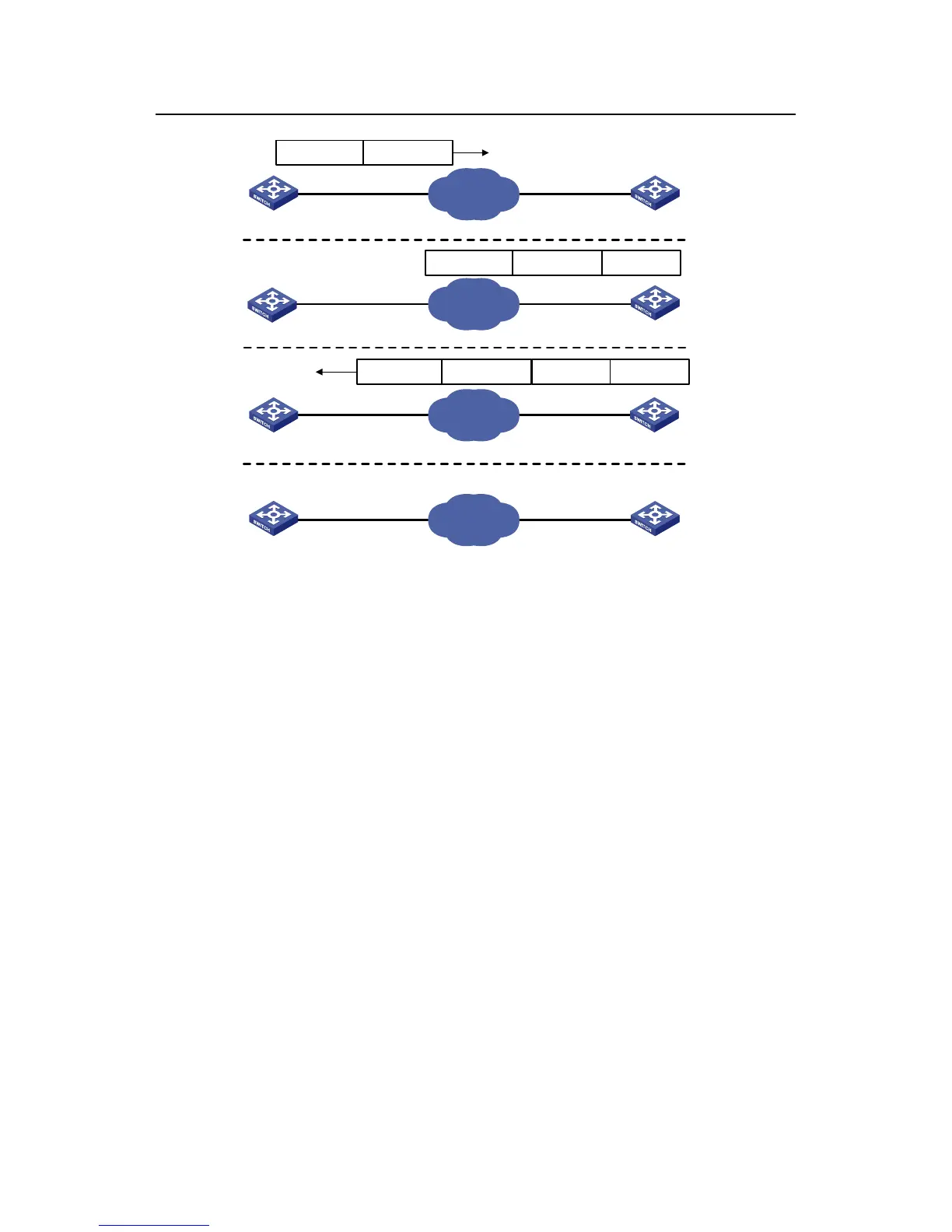
Figure 1-1 Implementation principle of NTP
The procedure of synchronizing the system clock is as follows:
z Device A sends an NTP message to Device B, with a timestamp 10:00:00 am (T
1
)
identifying when it is sent.
z When the message arrives at Device B, Device B inserts its own timestamp
11:00:01 am (T
2
) into the packet.
z When the NTP message leaves Device B, Device B inserts its own timestamp
11:00:02 am (T
3
) into the packet.
z When receiving a response packet, the local time of Device A is 10:00:03 am (T4).
At this time, Device A has enough information to calculate the following two
parameters:
z Delay for an NTP message to make a round trip between Device A and Device B:
Delay = (T
4
-T
1
)-(T
3
-T
2
).
z Time offset of Device A relative to Device B:
Offset = ((T
2
-T
1
) + (T
3
-T
4
))/2.
Device A can then set its own clock according to the above information to synchronize
its clock to that of Device B.
For detailed information, refer to RFC 1305.

 Loading...


