Operation Manual – NTP
H3C S3100 Series Ethernet Switches Chapter 1 NTP Configuration
1-21
z Device A and Device D are two S3100 Ethernet switches. Configure Device A and
Device D to work in the NTP broadcast client mode and listen to broadcast
messages through their own Vlan-interface2.
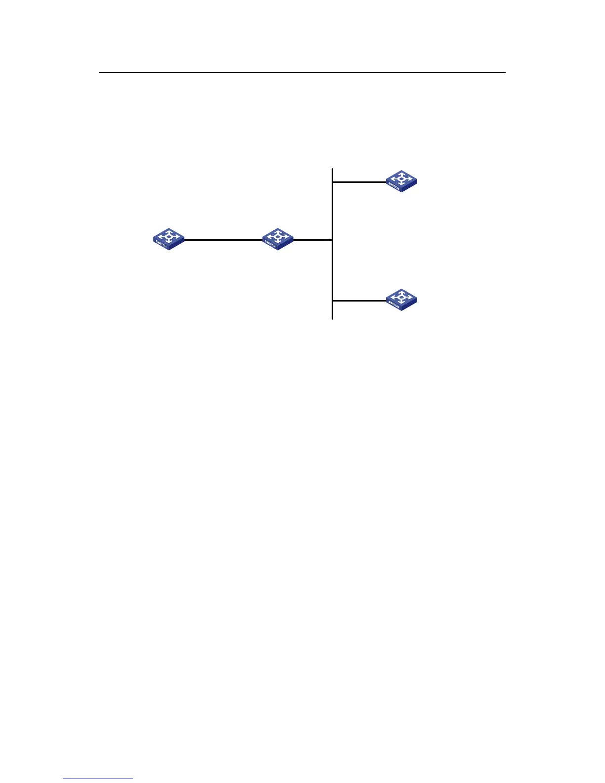
II. Network diagram
Vlan-int2
1.0.1.31/24
Vlan-int2
3.0.1.31/24
Vlan-int2
3.0.1.32/24
Device A Device B
Device C
Device D
Figure 1-8 Network diagram for the NTP broadcast mode configuration
III. Configuration procedure
1) Configure Device C.
# Enter system view.
<DeviceC> system-view
# Set Device C as the broadcast server, which sends broadcast messages through
Vlan-interface2.
[DeviceC] interface Vlan-interface 2
[DeviceC-Vlan-interface2] ntp-service broadcast-server
2) Configure Device A. (perform the same configuration on Device D)
# Enter system view.
<DeviceA> system-view
# Set Device A as a broadcast client.
[DeviceA] interface Vlan-interface 2
[DeviceA-Vlan-interface2] ntp-service broadcast-client
After the above configurations, Device A and Device D will listen to broadcast
messages through their own Vlan-interface2, and Device C will send broadcast
messages through Vlan-interface2. Because Device A and Device C do not share the
same network segment, Device A cannot receive broadcast messages from Device C,
while Device D is synchronized to Device C after receiving broadcast messages from
Device C.

 Loading...


