Programming technology functions (cycles)
9.4 Milling
Turning
Operating Manual, 01/2015, 6FC5398-8CP40-5BA2
467
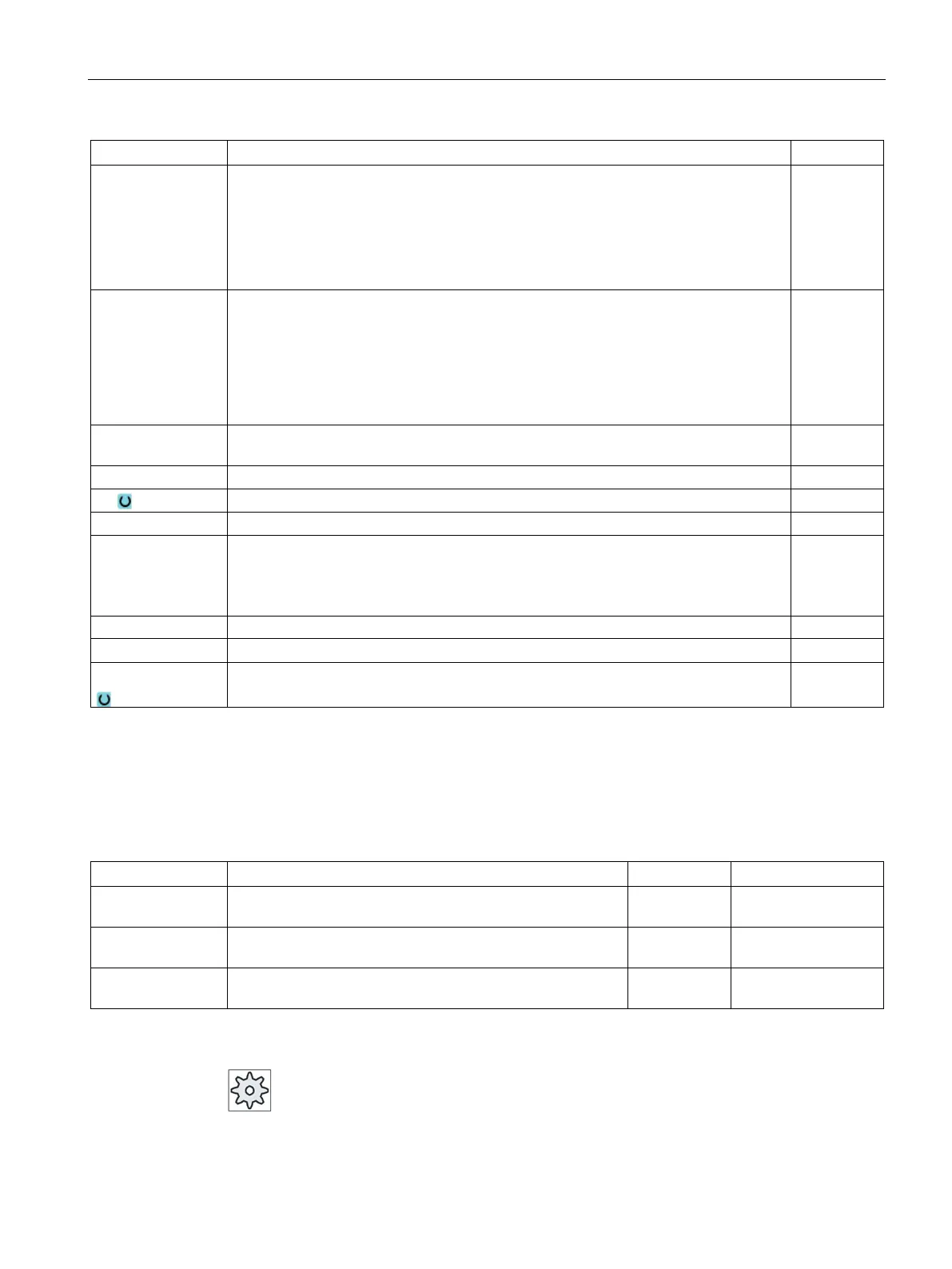
Y0 or C0
Z0
X0(only for Shop-
: The positions refer to the reference point:
Reference point Y or reference point angle polar
Reference point Z
Cylinder diameter ∅
mm or de-
grees
mm
mm
C0
Y0
Z0
X0
: The positions refer to the reference point:
Positioning angle for machining surface
Reference point Y
Reference point Z
Reference point X
Degrees
mm
mm
mm
∅1 Diameter of blank spigot (important for determining approach position) - (only for ∇ and
mm
Depth relative to Z0 or X0 (inc) or spigot depth (abs) - (only for ∇ and ∇∇∇)
Maximum depth infeed – (only for ∇ and ∇∇∇)
UXY Plane finishing allowance for the length (L) and width (W) of the rectangular spigot.
Smaller rectangular spigot dimensions are obtained by calling the cycle again and
programming it with a lower finishing allowance.
mm
Depth finishing allowance (tool axis) - (only for ∇ and ∇∇∇)
FS Chamfer width for chamfering - (for chamfering only) mm
ZFS
Insertion depth of tool tip (abs and inc) - (for chamfering only)
(ZFS for machining surface, face C/Y or XFS for peripheral surface C/Y)
mm
* Unit of feedrate as programmed before the cycle call
The following parameters are hidden. They are pre-assigned fixed values or values that can
be adjusted using setting data.
PL (only for G
Machining plane Defined in MD
SC (only for G
Safety clearance 1 mm x
Machining
Mill circular spigot at the programmed position (X0, Y0, Z0). Single posi-
Please refer to the machine manufacturer's specifications.