Tool management
12.5 Tool list
Turning
Operating Manual, 01/2015, 6FC5398-8CP40-5BA2
679
All parameters and functions that are required to create and set up the tools are displayed in
the tool list.
Each tool is uniquely identified by the tool identifier and the replacement tool number.
For the tool display, i.e. when displaying the cutting edge positions, the machine coordinate
system is taken into account.
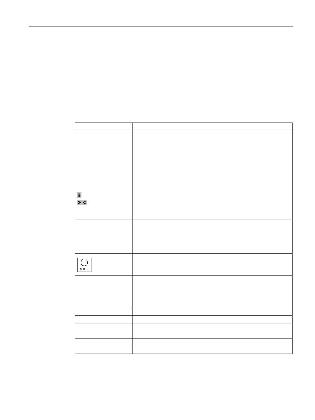
Location
BS
*
*
* If activated in magazine
Magazine/location number
• The magazine location numbers
The magazine number is specified first, followed by the location num-
ber in the magazine.
If there is only one magazine, only the location number is displayed.
• Load position in the load magazine
The following icons can also be displayed for other magazine types (e.g.
for a chain):
• Spindle location as an icon
• Locations for gripper 1 and gripper 2 (applies only when a spindle with
dual gripper is used) as icons.
Type
Tool type
Specific tool offset data is displayed depending on the tool type (repre-
sented as an icon).
The icon identifies the position of the tool; this was selected when the tool
You have the option of changing the tool position or the tool type using
the <SELECT> key.
Tool name The tool is identified by the name and the replacement tool number. You
can enter the name as text or number.
: The maximum length of tool names is 31 ASCII characters. The
number of characters is reduced for Asian characters or Unicode charac-
ters. The following special characters are not permitted: | # ".
Replacement tool number (for replacement tool strategy).
Length X, length Z Tool length
Geometry data length X and length Z