Setting up the machine
3.5 Measuring the tool
Turning
Operating Manual, 01/2015, 6FC5398-8CP40-5BA2
83
Select the direction (+ or
-), in which you would like to approach the tool
Position the calibrating tool in the vicinity of the tool probe in such a way
that any collisions can be avoided when the first point of the tool probe
is being approached.
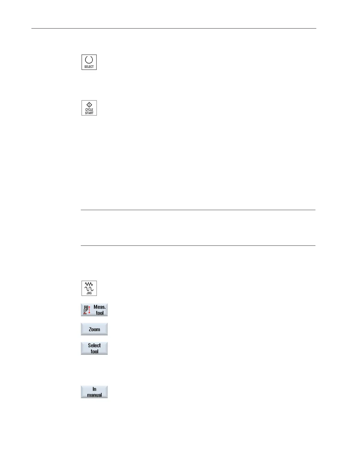
Press the <CYCLE START> key.
The calibration process is started, i.e. the calibrating tool is automatica
l-
versed at the measurement feedrate to the probe and back again.
The position of the tool probe is determined and saved in an internal
data area.
Repeat the process for the other other points of the tool probe.
Measuring a tool with a magnifying glass
You can also use a magnifying glass to determine the tool dimensions, if this is available on
the machine.
In this case, SINUMERIK Operate calculates the tool offset data from the known positions of
the tool carrier reference point and the cross-hairs of the magnifying glass.
Note
Lathes with B axis
For lathes with a B axis, execute the tool change and alignment in the T, S, M window before
performing the measurement.
Select the "JOG" mode in the "Machine" operating area.
Press the "Meas. tool" softkey.
Press the "Zoom" softkey.
the "Select tool” softkey.
The "Tool selection" window is opened.
Select the tool that you wish to measure.
The cutting edge position and the radius or diameter of the tool must
already be entered in the tool list.
Press the "In manual" softkey.
The tool is accepted in the "Zoom" window.