Programming technology functions (cycles)
9.5 Contour milling
Turning
538 Operating Manual, 01/2015, 6FC5398-8CP40-5BA2
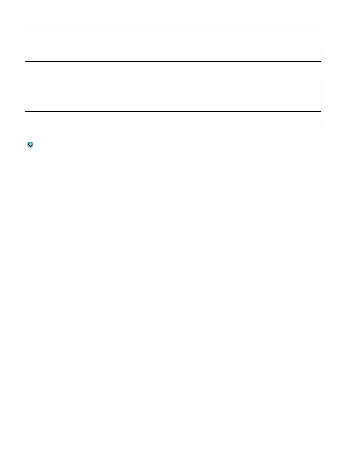
CP Positioning angle for machining area
- (only for ShopTurn, machining surface, face Y)
Degrees
C0 Positioning angle for machining surface
- (only for ShopTurn, machining surface, peripheral surface Y)
Degrees
DXY
• Maximum plane infeed
• Maximum plane infeed as a percentage of the milling cutter diameter
mm
%
UXY Finishing allowance, plane mm
Finishing allowance, depth
Lift mode
Lift mode before new infeed
If the machining operation requires several points of insertion, the retraction
height can be programmed:
• To retraction plane
• Z0 + safety clearance
When making the transition to the next insertion point, the tool returns to this
height. If there are no elements larger than Z0 (X0) in the pocket area, then Z0
(X0) + safety clearance can be programmed as the lift mode.
mm
mm
Milling contour pocket (CYCLE63)
Function
You can use the "Mill pocket" function to mill a pocket on the face or peripheral surface.
Before you remove stock from the pocket, you must first enter the contour of the pocket and,
if applicable, the contour of an island. Stock is removed from the pocket parallel to the
contour from the inside to the outside. The direction is determined by the machining direction
(climbing or conventional). If an island is located in the pocket, the cycle automatically takes
this into account during stock removal.
Note
Execution from external media
If you execute programs from an external drive (e.g. local d
rive or network drive) then you
require the execution from external storage function (EES).
For additional information, please refer to the following references:
Commissioning Manual SINUMERIK Operate (IM9) / SINUMERIK 840D sl