Programming technology functions (cycles)
9.5 Contour milling
Turning
548 Operating Manual, 01/2015, 6FC5398-8CP40-5BA2
1. The tool approaches the starting point at rapid traverse at the height of the retraction
plane and is fed in to the safety clearance. The cycle calculates the starting point.
2. The tool first infeeds to the machining depth and then approaches the spigot contour from
the side in a quadrant at machining feedrate.
3. The spigot is machined in parallel with the contours from the outside in. The direction is
determined by the machining direction (climb/conventional) (see "Changing program
settings").
4. When the first plane of the spigot has been machined, the tool retracts from the contour in
a quadrant and then infeeds to the next machining depth.
5. The spigot is again approached in a quadrant and machine in parallel with the contours
from outside in.
6. Steps 4 and 5 are repeated until the programmed spigot depth is reached.
7. The tool retracts to the safety clearance at rapid traverse.
The part program or ShopTurn program to be p
rocessed has been cre-
ated and you are in the editor.
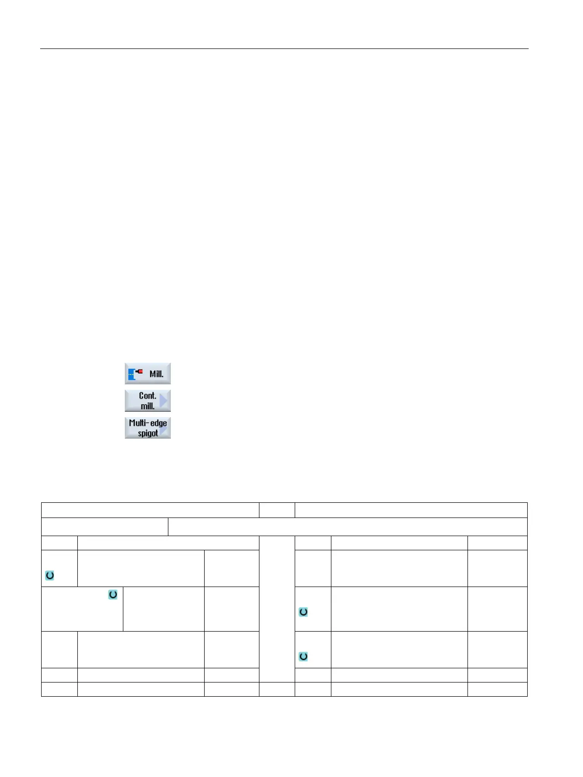
Press the "Milling", "Contour milling" and "Spigot" softkeys.
The "Mill spigot" input window opens.
Select the "Roughing" machining type.
Parameters in the "Input complete" mode
Parameters, G code program
Parameters, ShopTurn program
Input
• Complete
Name of the program to be generated
PL
Machining plane D Cutting edge number
Milling direction
• Climbing
• Conventional
milling
F
Feedrate mm/min
mm/tooth
RP Retraction plane mm S / V
Spindle speed or constant cut-
ting rate
rpm
m/min