Names and Functions of Parts of the Control Panel 33
• The buttons in this row select the key 1 or
key 3 signals to be inserted into the video
on this M/E bank or PGM/PST bank.
• To select the key 1 fill signal, check that the
right-hand [KEY3] button in the M/E bank
(or the [DSK3] button in the PGM/PST
bank) is off, then press the button assigned
to the desired signal.
• To select the key 3 fill signal, press the
[KEY3] button, turning it on.
• While the [UTIL] button on the right hand
side is held down, these buttons are
assigned to the DME external video bus
allowing you to select the signal on that
bus.
Chapter
2
Menus
and
Control
Panel
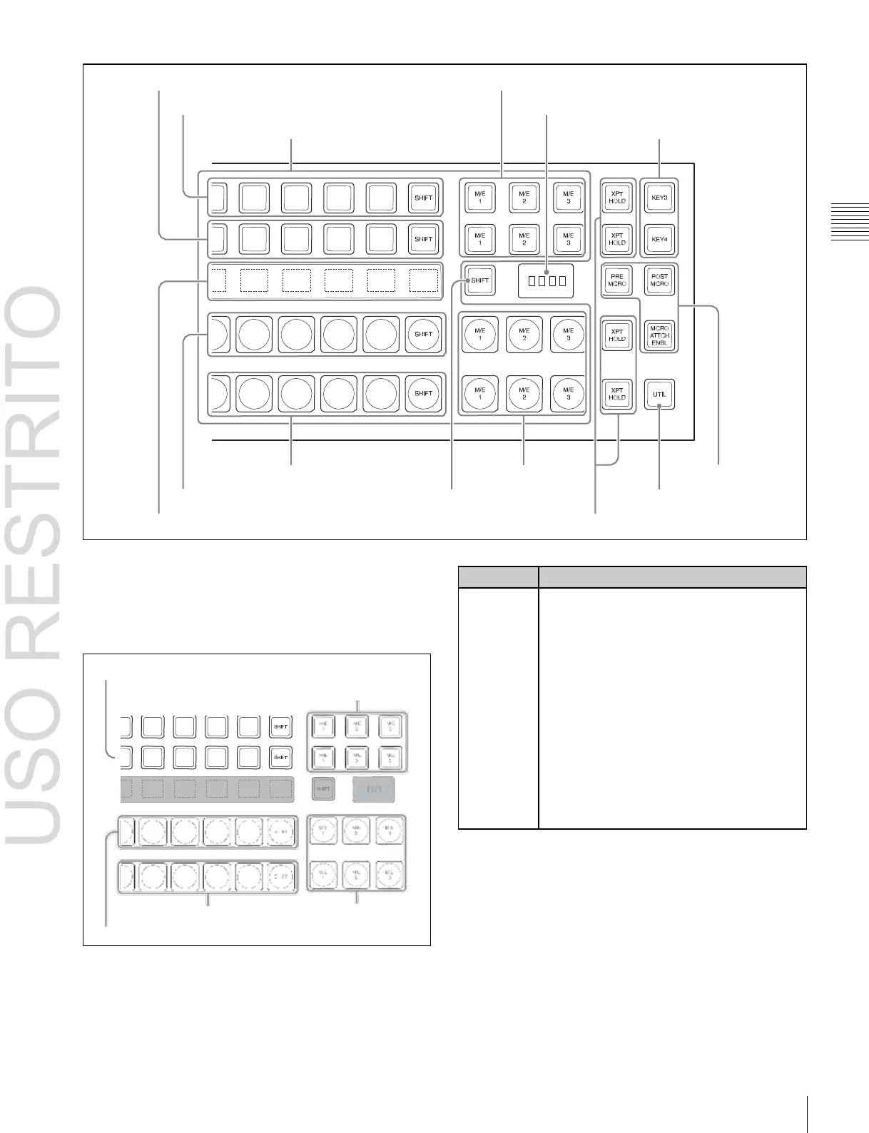
Key 2 row
Reentry buttons
Key 1 row
1
Cross-point buttons
7
M/E bank display
3
Key bus selection buttons
Background B row
Reentry buttons
8
Macro buttons
Background A row
5
Source name displays
6
Dedicated SHIFT button
4
UTIL button
2
XPT HOLD buttons
a
Cross-point buttons
These buttons select the signals used for video creation on
this M/E bank or PGM/PST bank. Each row of buttons
corresponds to one or more signal buses within the
switcher.
Key 2 row
Key 1 row Reentry buttons
Background B row Reentry buttons
Background A row
For details of assignment and selection of keys 5 to 8, see
the following sections in Appendix: “Assigning Buttons for
Selection of Keys 5 to 8 in the Setup Menu” (page 397) and
“Selecting Input Signals for Keys 5 to 8 in the Cross-Point
Control Block” (page 398).

 Loading...


