Interfacing With External Devices (Device Interface Menu) 599
a) 1: Field 1, 2: Field 2, 3: Any
When “ ” is selected as the trigger polarity, there is
no Pulse Width setting. When “Status” is selected,
there is no Pulse Width or Timing setting.
In the <Source> group, select the action block.
M/E-1 to M/E-5 and P/P: Set an action for the M/E or
Chapter
19
Control
Panel
Setup
(Panel)
Carrying out level settings
To set the low level and high level, first set the trigger type
to “Level,” then use the following procedure.
1
In the Panel >Device Interface >GPI Input menu,
select the action to be set, and press [H/L Set].
The H/L Set menu appears.
2
Using any of the following methods, select the
settings.
•
Press directly on the list in the status area.
•
Press the arrow keys to scroll the reverse video
cursor.
•
Turn the knob.
Signal format/
screen aspect
ratio selection
3
To apply the selection made in step 2 when the input
is the GPI high level, press [H Set]. To apply the
selection made in step 2 when the input is low, press
[L Set].
This confirms the setting, which appears in the status
area.
To set the level for the format converter
1
Set “Action” to “System Format” in step 5 of “Making
Control Panel GPI Input Settings” (page 597).
The format converter list appears.
2
Select the format converter that you want to set from
the list.
3
In the <FC Input/Output> group, press [H Set] or [L
Set] to set the high level or low level, respectively.
Making Control Panel GPI Output
Settings
1
In the Panel >Device Interface menu, press [GPI
Output].
The GPI Output menu appears.
2
Using any of the following methods, select the
settings.
•
Press directly on the list in the status area.
•
Press the arrow keys to scroll the reverse video
cursor.
•
Turn the knob.
3
In the <Trigger Type> group, select the trigger
polarity.
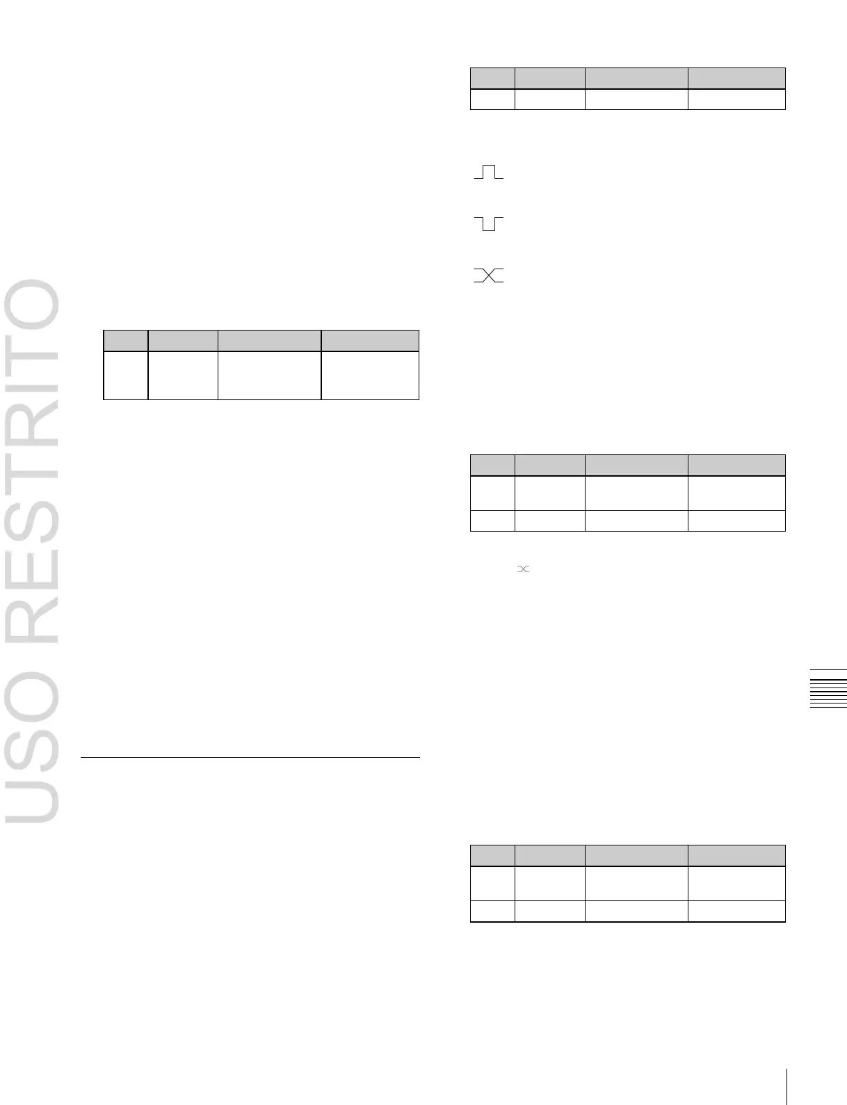
(Rising Edge): The trigger causes the relay to
open or the output to go high level, and holds this
state for the specified pulse width duration.
(Falling Edge): The trigger causes the relay to
close or the output to go low level, and holds this
state for the specified pulse width duration.
(Any Edge): When a trigger occurs, the relay
opens/closes or the output goes high/low level,
switching state.
Status: The relay opens/closes or the output goes
high/low level in response to the status.
No Operation: The trigger has no effect on the relay
state or output level.
4
Turning the knobs, select the pulse width and timing to
be set.
PGM/PST bank.
Common: Set an action for error status.
6 Using any of the following methods, select the action
to be set.
•
Press directly on the list in the status area.
•
Press the arrow keys to scroll the reverse video
cursor.
•
Turn the knobs.
a)
Action list when the trigger type is other than “Status”
In M/E-x, the x is the M/E bank number (1 to 5); in DSKx the x is the
DSK number (1 to 8); in Keyx the x is the key number (1 to 8).
When Source is M/E-x: Keyx SS ? Recall, No Action
When Source is P/P: DSKx SS ? Recall, No Action
When Source is Common: KF Run, No Action
Action list when the trigger type is “Status”

 Loading...


