GPI Input Setting (GPI Input Assign Menu) 641
Chapter
22
DCU
Setup
(DCU)
GPI Input Setting (GPI
Input Assign Menu)
a) When the MKS-2700 is connected, select a value in the range 1 to 34.
4
To confirm the assignment in step 3, press [GPI Input
Set].
This assigns the GPI input, and this is reflected in the
status area.
Releasing the Assignment of a GPI
Input Port
1
In the DCU >Input Config menu, select what the
setting applies to (DCU1 or DCU2) from the <DCU
Select> group.
2
In the <Parallel Input Assign> group, if [GPI Input] is
on, press it to turn it off.
3
Turn the knobs to adjust the following parameters.
To set the trigger type and so on for each GPI input, display
the DCU >GPI Input Assign menu.
To display the GPI Input Assign menu
In the Engineering Setup menu, select VF5 ‘DCU’ and
HF2 ‘GPI Input Assign.’
The GPI input port setting status appears in the status area.
Making DCU GPI Input Settings
1 In the DCU >GPI Input Assign menu, using any of the
following methods select what the setting applies to.
•
Press directly on the list in the status area.
•
Press the arrow keys to scroll the reverse video
cursor.
•
Turn the knob.
4 In the <Parallel Input Assign> group, press [No
Assign].
2
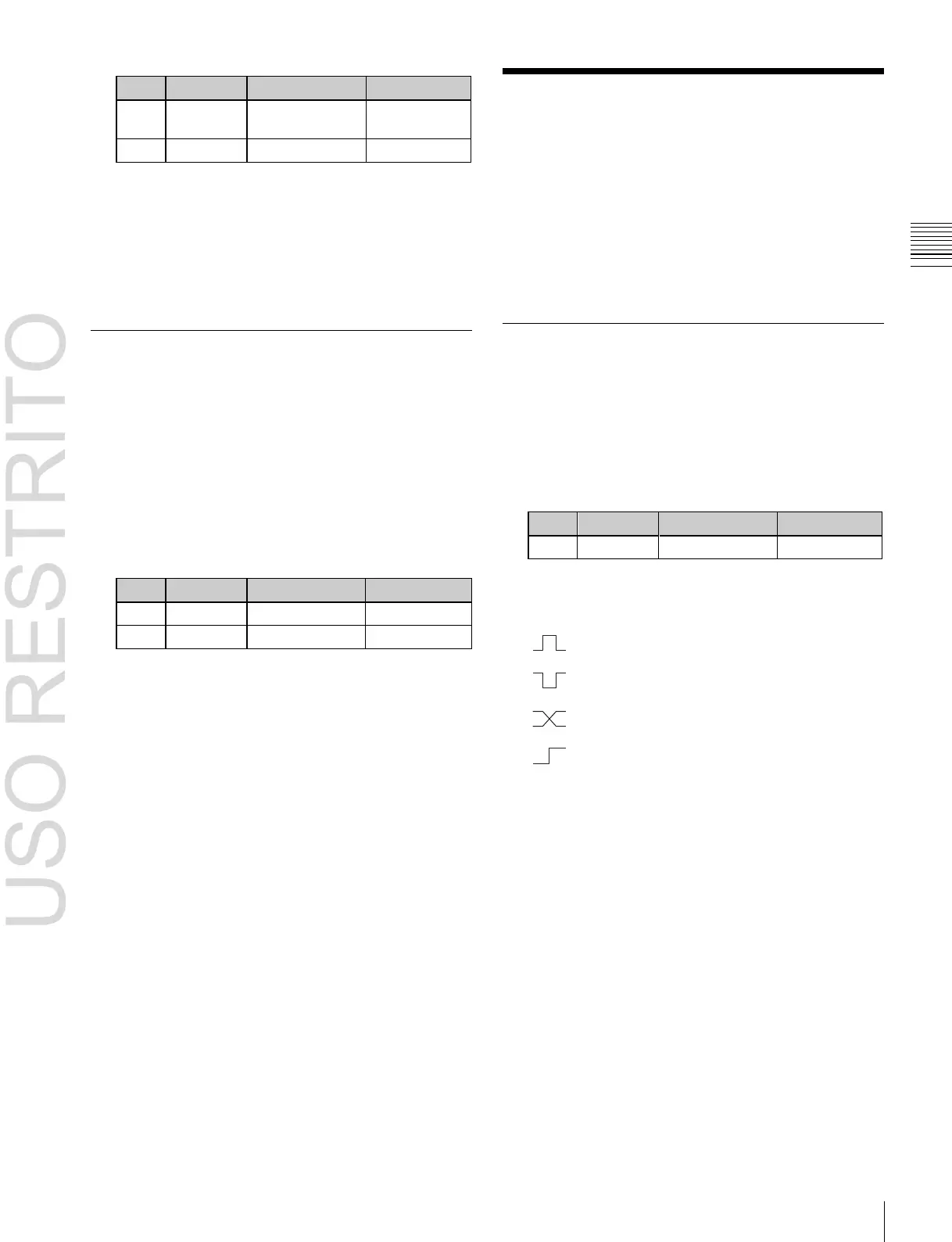
In the <Trigger Type> group, select the trigger
polarity.
(Rising Edge): Apply the trigger on a rising
edge of an input pulse.
(Falling Edge): Apply the trigger on a falling
edge of an input pulse.
(Any Edge): Apply the trigger on a change in
the polarity of the input signal.
(Level): Carry out the specified operation when
the input is low or high.
No Operation: Apply no trigger on an input pulse.
3
In the <Target Device> group, select the control panel
to handle the GPI input.
SCU1: ID1 control panel (PNL1)
SCU2: ID2 control panel (PNL2)
SCU3: ID3 control panel (PNL3)
The action set in the following step 4 is executed for
the switcher and DME controlled by the selected
control panel.
4
Using any of the following methods, select the action
you want to set.
•
Press directly on the list in the status area.
•
Press the arrow keys to scroll the reverse video
cursor.
•
Turn the knobs.

 Loading...


