The user source name file is exported to the memory
card.
To apply the signal pairs in the patch table to this
menu
Press [Apply Patch Tbl].
For more information about the patch table, see the
following item.
User source name
Signal pairs
Creating a Patch Table (Conversion
Table)
Load the memory card created in Switcher A to Switcher
B, and use the following procedure in Switcher B.
1 In the User Setup menu, select VF1 ‘Source Patch’ and
HF2 ‘Patch Table.’
The Patch Table menu appears.
5 Using either of the following methods, select the target
user source name from the list on the left.
•
Press directly on the list in the status area.
•
Press the arrow keys to scroll the reverse video
cursor.
•
Turn the knob.
User source
name
selection
2
Press [File >Imp Usr Src Name].
The Import Usr Src Name menu appears.
3
Select Memory Card as the import source, and press
[
T
Import].
The user source name file is loaded from the memory
card.
4
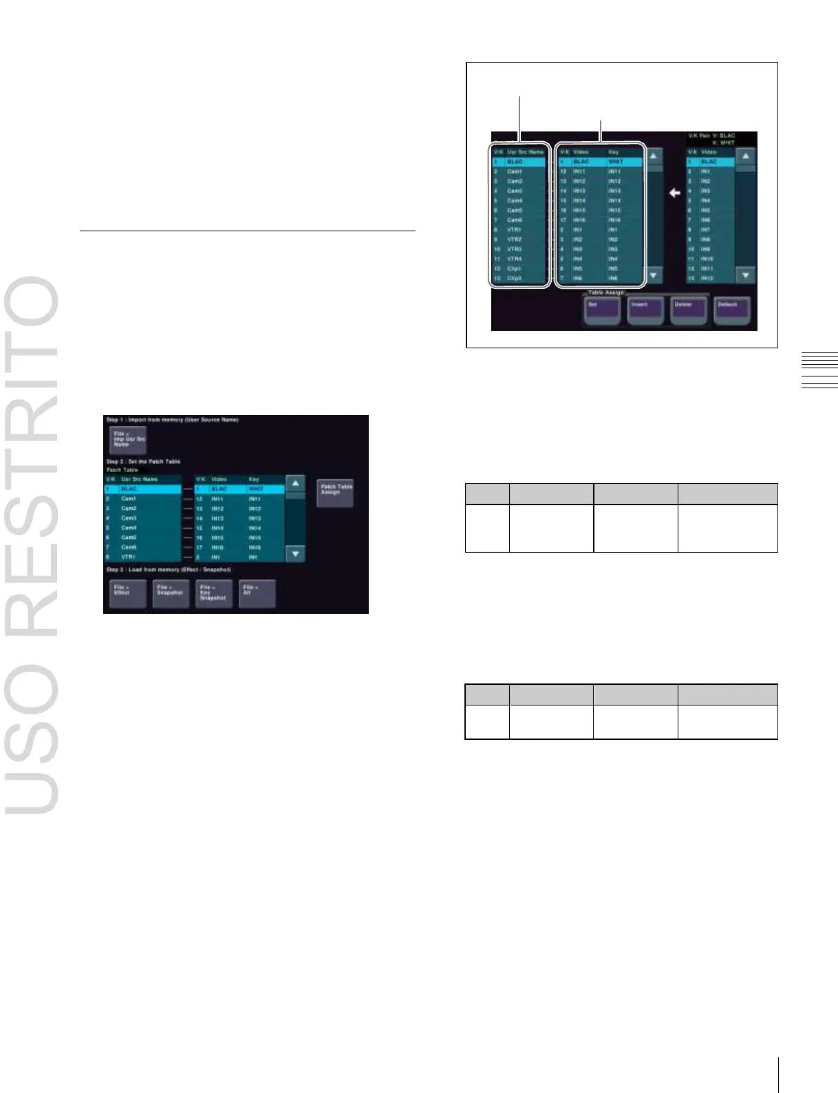
Press [Patch Table Assign].
The Patch Table Assign menu appears.
The user source names in Switcher A imported by step
3 are listed on the left and the pairs of videos and keys
set in Switcher B are listed on the right.
6
Using either of the following methods, select the video
signal that you want to assign from the list on the right.
•
Press directly on the list in the status area.
•
Press the arrow keys to scroll the reverse video
cursor.
•
Turn the knob.
7
In the <Table Assign> group, press [Set].
The video/key signal name selected in the list on the
right is reflected in the list on the left.
8
Repeat steps 5 to 7 to create a patch table.
It is also possible to execute the following editing
operations using the buttons in the <Table Assign>
group.
•
Press [Insert] to insert a signal name above the signal
name selected in the list on the left.
•
Press [Delete] to delete the signal name selected in
the list on the left.

 Loading...


