Names and Functions of Parts of the Control Panel
Apply a border of a uniform thickness to the
whole key.
DROP BDR
(drop
border)
a)
Apply a border to two sides of the key (for
example, below and to the right, or below and
to the left).
Apply a shadow to two sides of the key (for
example, below and to the right, or below and
to the left).
• Use the outline of the key.
• Use the key fill signal selected for the key in
the edge portions.
• Apply an embossing effect to the periphery
of the key.
• When emboss is selected, you can use the
dedicated color matte signal for the emboss
function.
Press this button, turning it on, to enable the
key mask using the main pattern.
Press this button, turning it on, to enable the
key mask using the sub pattern.
Press this button, turning it on, to insert a
translucent pattern behind the key.
Press this button, turning it on, to soften the
key edge portions.
• Hold down this button and press the
selection button for the DME channel you
want to assign to the monitor output; you
can then monitor the output signal on the
DME monitor output.
• While this button is held down, the DME
channel selection buttons light as follows,
allowing you to check the monitor
assignment.
Lit amber: DME channel that can currently
be monitored
Lit green: DME channel currently assigned
to the monitor output
Chapter
2
Menus
and
Control
Panel
(border)
(shadow)
a) When one of these buttons is selected, you can use a special color matte or
a signal selected on the utility 1 bus for the edge.
e
MORE button
When there are more than four parameters, this button
lights amber. When it is pressed, it changes from amber to
green and the fifth and subsequent parameters are assigned
to the knobs, allowing them to be adjusted.
f
SHOW KEY button
While this button is held down, a key processed key source
signal is output from the specified output port. You can
make the output specification independently for the edit
preview and the preview of each M/E or PGM/PST bank
in the Setup menu.
g
Knobs
Turn the knobs to adjust the parameter values.
h
Displays
Each display shows the initial letters of the parameter
name and the parameter value (maximum three digits
including a minus sign for a negative value).
i
DME channel selection buttons
Press one of these buttons, turning it on, to delegate a DME
channel to the keyer.
The number of valid DME channel selection buttons
depends on the number of channels installed in the DME
processor.
A maximum of four consecutively numbered DME
channels from the two sets, DME 1 to 4 and DME 5 to 8,
can be assigned to one keyer.
On the MVS-8000X, when the signal format is 1080P
only, the consecutive channel combinations that can be
selected are any of DME1 and DME2, DME3 and DME4,
DME5 and DME6, or DME7 and DME8.
On the MVS-7000X, when the signal format is 1080P, the
above restriction also applies if using the MVE-8000A.
There is no such restriction for the MKS-7470X/7471X.
DME channel assigned to a keyer cannot be selected on
another keyer.
However, using the override function it is possible to
allocate a channel already allocated to another keyer to the
currently selected keyer. If DME channel allocations have
been made in a Setup menu, these buttons cannot be used
to make DME channel allocations. Using the trace
function, it is possible to check which keyer a DME
channel is allocated to.
j
ON AIR indicators
These light red when the corresponding DME channels are
included in the final program output.
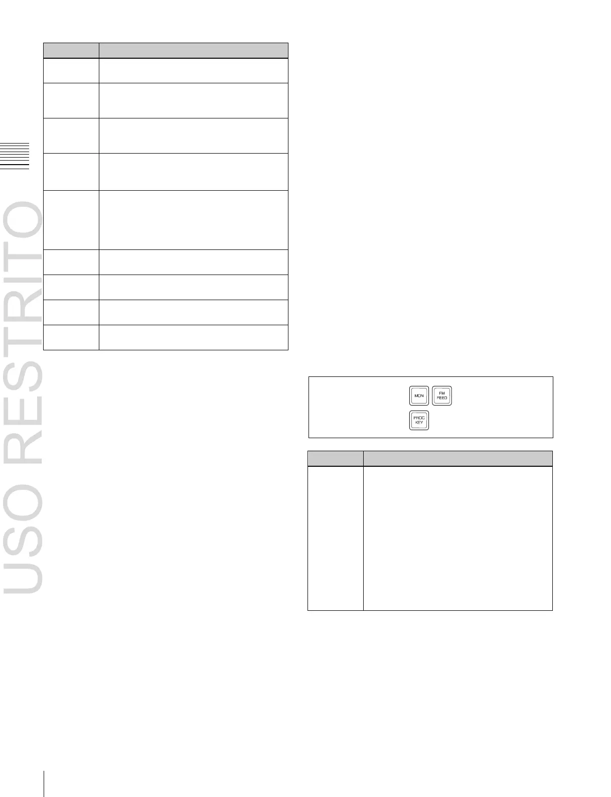
k
Output destination specification buttons
Pressing the following buttons selects and checks the
output signal.

 Loading...


