Reference Manual ADuCM356
LOW-POWER POTENTIOSTAT AMPLIFIERS AND LOW-POWER TIAS
analog.com Rev. A | 86 of 312
6-Bit DAC Output Voltage = 0.2 V + (LPDACDATx,
Bits[17:12] × 34.38 mV)
(8)
When the 12-bit output is greater than or equal to 6-bit output,
12-Bit DAC Output Voltage = 0.2 V + (LPDACDATx,
Bits[11:0] × 0.54 mV) + 0.54 mV
(9)
6-Bit DAC Output Voltage = 0.2 V + (LPDACDATx,
Bits[17:12] × 34.38 mV)
(10)
where 0.54 mV is approximately 1 LSB of the 12-bit DAC and 34.38
mV is approximately 1 LSB of the 6-bit DAC.
In user code, it is recommended to add the following:
12BITCODE = LPDACDATx[11:0];
6BITCODE = LPDACDATx[17:12];
if (12BITCODE > (6BITCODE *64))
LPDACDATx[11:0] = (12BITCODE – 1);
If LPDACDATx, Bits[11:0] = 4095, the minimum voltage on the
12-bit output is 2.39946 V, because LPDACDATx, Bits[11:0] = 4095
has the same effect as LPDACDATx, Bits[11:0] = 4094.
Low-Power DAC Use Cases
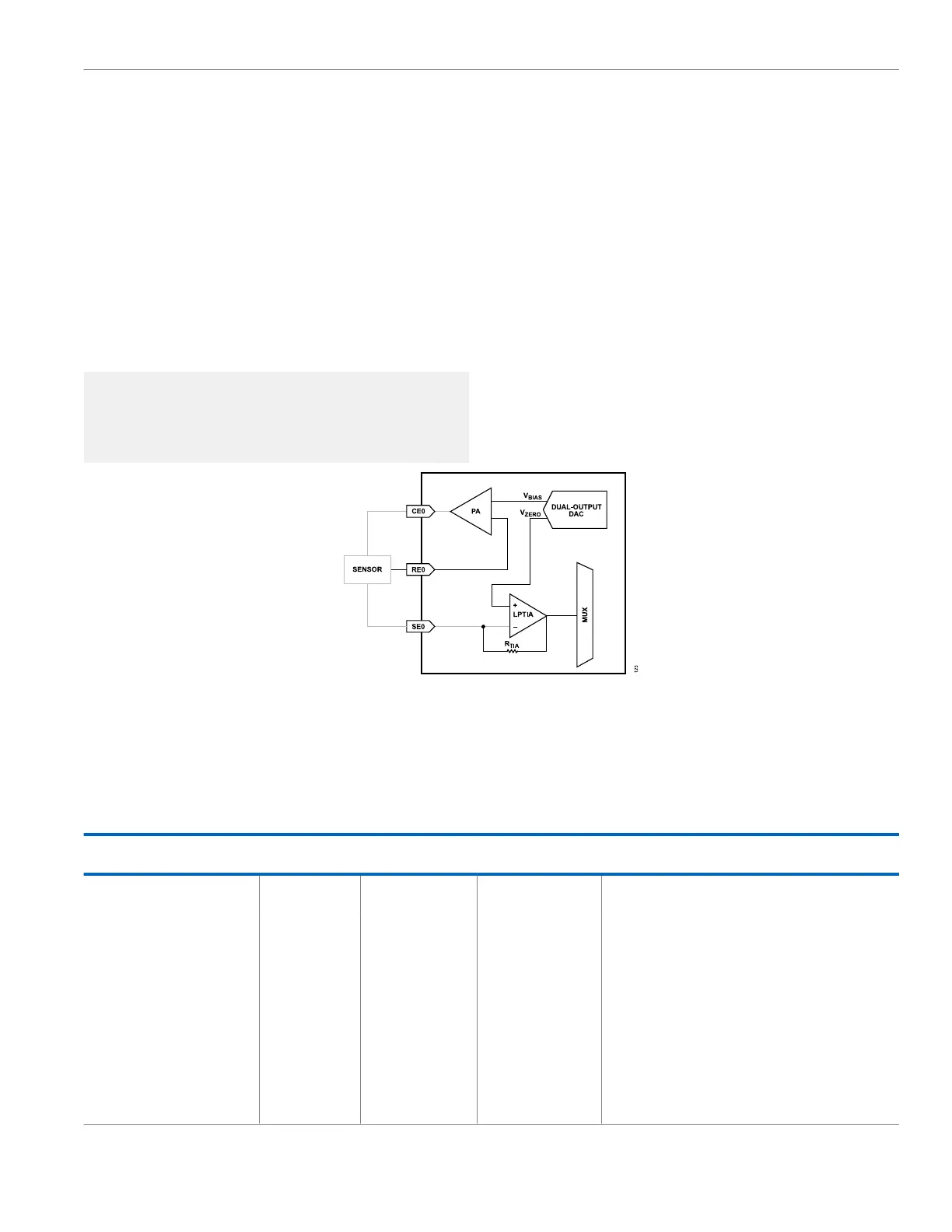
Electrochemical Amperometric Measurement
In an electrochemical measurement, the 12-bit output sets the
voltage on the reference electrode pin via the potentiostat circuit
shown in Figure 20. The voltage on the CE0 and RE0 pins is V
BIAS
.
The 6-bit output sets the bias voltage on the low-power TIA positive
pin, which in turn sets the voltage on SE0. This voltage is V
ZERO
.
The bias voltage on the sensor effectively becomes the difference
between the 12-bit output and the 6-bit output.
Figure 20. Electrochemical Standard Configuration
Recommended Switch Settings for Various
Operating Modes
Table 106 details the recommended switch settings in the low-pow-
er potentiostat loop for various measurement types. For all meas-
urement types, setting to 1 closes the switch and setting to 0 opens
the switch. LPTIASWx, Bits[13:0] control SW13 to SW0 in Figure 16
and Figure 17.
Table 106. Recommended Switch Settings in Low-Power Potentiostat Loop
Measurement Name
LPDACCONx Bit 5
Setting
LPDACSWx Bits[5:0]
Setting
LPTIASWx Bits[13:0]
Setting Description
Amperometric Mode 0 0xXX (don’t care) 0x302C or 0b11 0000
0010 1100
Normal DC current measurement. External capacitors to
VBIASx and VZEROx DACs are connected.
Amperometric Mode with Diode
Protection
0 0xXX (don’t care) 0x302D or 0b11 0000
0010 1101
Normal DC current measurement with low-power TIA back to
back diode protection enabled. External capacitors to VBIASx
and VZEROx DACs connected.
Amperometric Mode with Short
Switch Enabled
0 0xXX (don’t care) 0x302E or 0b11 0000
0010 1110
Normal DC current measurement with short switch protection
enabled. SW1 is closed to connect the sense electrode input
to the output of the low-power TIA. External capacitors to
VBIASx and VZEROx DACs connected. Useful if external
sensor must be charged after a power-up and many currents
flow in or out of the SEx pin.
Amperometric Mode for Zero-Biased
Sensor
0 0xXX (don’t care) 0x306C or 0b11 0000
0110 1100
Amperometric mode with SW6 configured to set sensors
reference electrode and sense electrode to VBIASx level.
Potentiostat amplifier inverting and low-power TIA noninverting
 Loading...