Dolby
®
IMS2000 Installation and User’s Manual
IMS.OM.004730.DRM Issue 3 13
4.14 AES Out 9–16
• Digital audio channels 1–8 output
• RJ-45 connector
Table 4-4 AES Out 9–16 Pin Number and Description
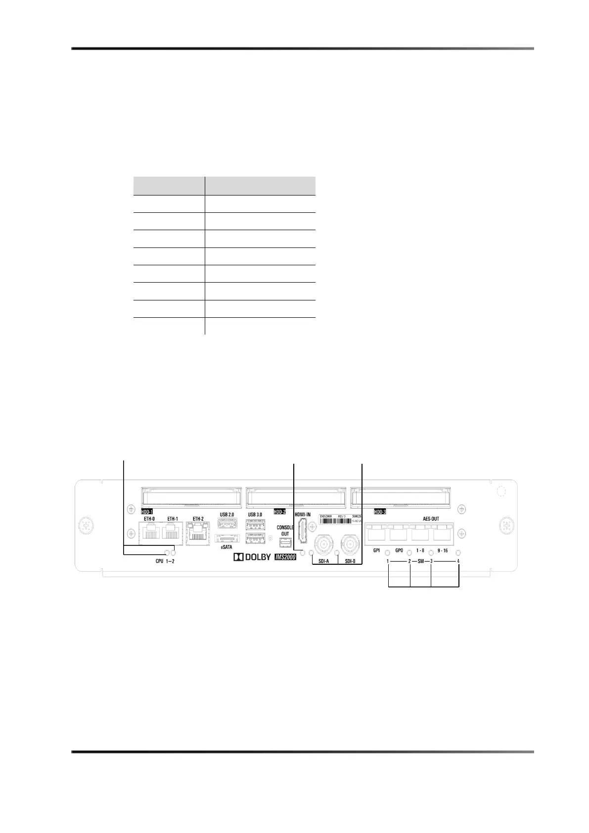
4.15 LEDs
See the following figure for LED placement.
Figure 4-3 IMS2000: Front View
For more information, see Chapter 24.
Pin Number Description
1 Channel 9 and 10 plus
2 Channel 9 and 10 minus
3 Channel 11 and 12 plus
4 Channel 13 and 14 plus
5 Channel 13 and 14 minus
6 Channel 11 and 12 minus
7 Channel 15 and 16 plus
8 Channel 15 and 16 minus