4 - 41
Chapter 4 Disassembly / Assembly and Adjustments
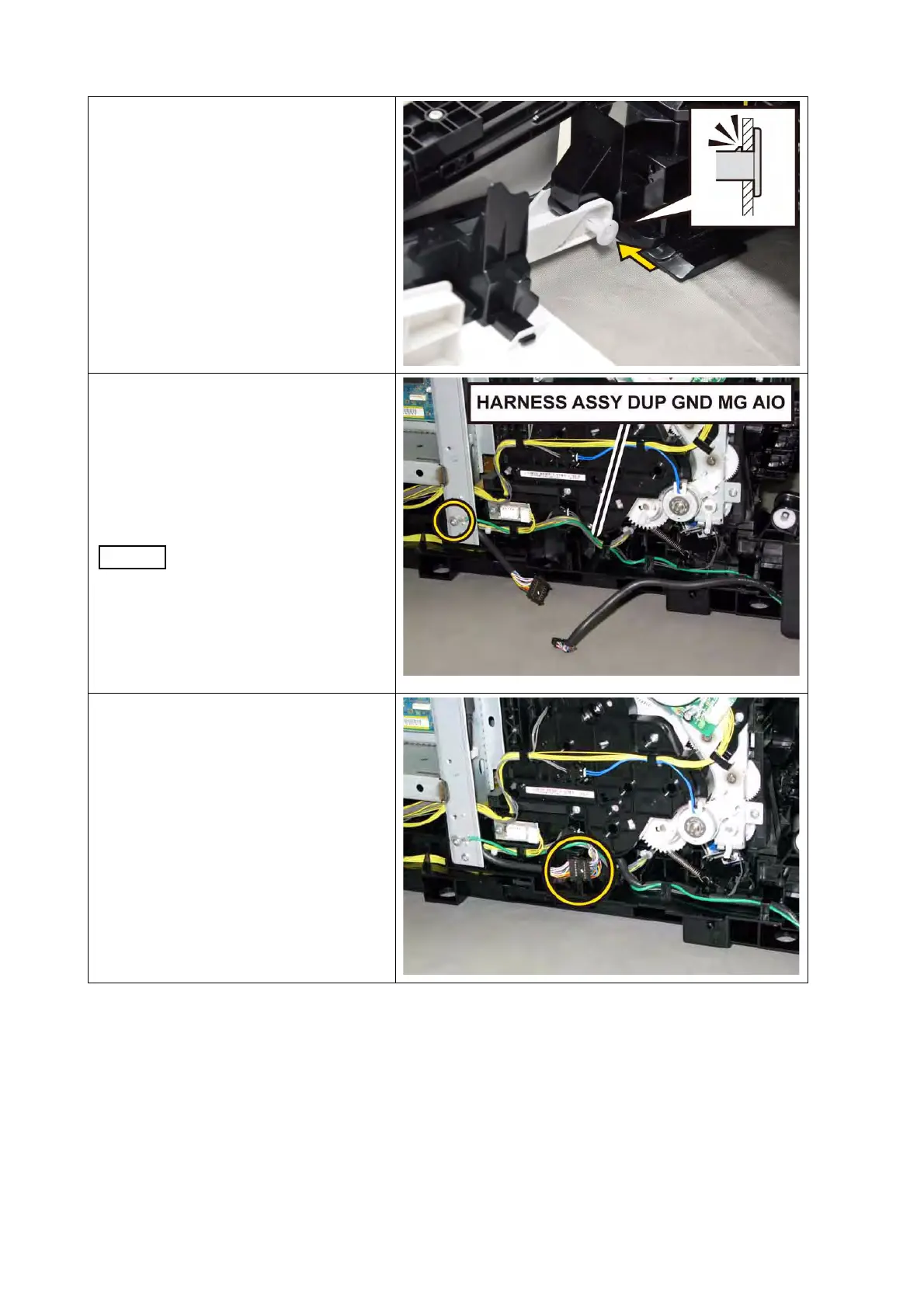
4) Mate the flat face of the SHAFT
PIVOT with the hole of the COVER
ASSY FRONT, push the left side
SHAFT PIVOT until the hook is
locked.
5) Route the HARNESS ASSY DUP
GND MG AIO along the hooks of the
printer, secure the grounding termi-
nal of the HARNESS ASSY DUP
GND MG AIO with the one screw
(silver, 6mm).
This step is only duplex
model.
6) Route the HARNESS ASSY PNL A
through the hooks of the printer,
engage the connector (P/J5301) of
the HARNESS ASSY PNL A. Secure
the relay connector with the rib of
the printer.

 Loading...