4 - 128
Chapter 4 Disassembly / Assembly and Adjustments
[Replacement]
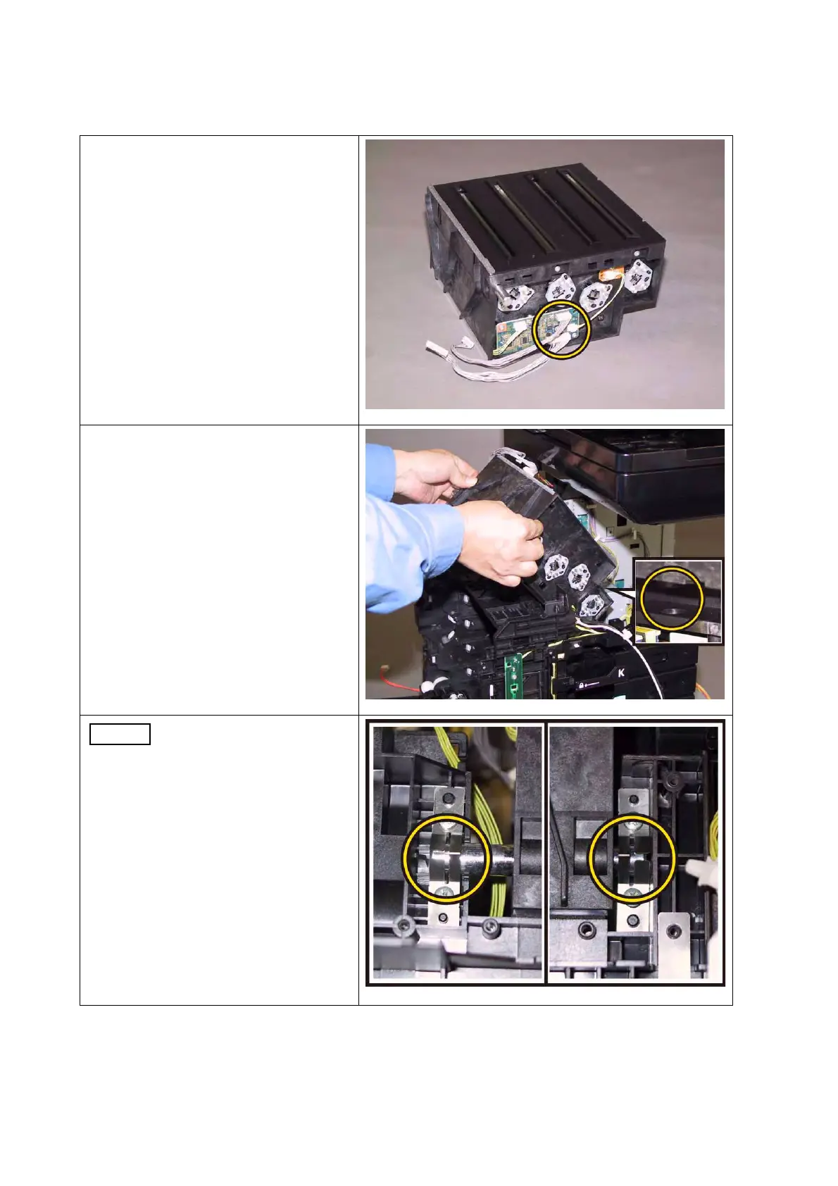
1) Engage the two connectors (P/J411
and 412) of the ROS ASSY.
2) Mate the under side boss of the ROS
ASSY with the hole of the printer,
attach the ROS ASSY.
When carrying out the work
described next procedure,
ensure that the SPRING
ROS is oriented to the
direction shown in the
right.
 Loading...