4 - 193
Chapter 4 Disassembly / Assembly and Adjustments
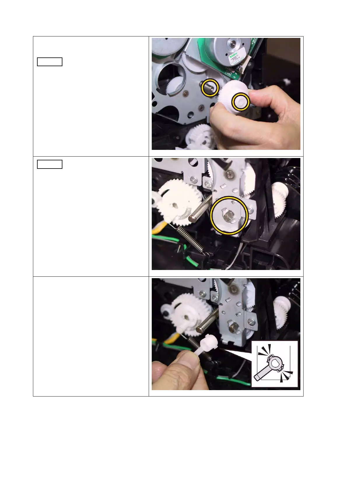
3) Attach the GEAR P2 to the shaft of
DRIVE ASSY SUB.
Ensure that the GEAR P2 is
oriented to the direction
shown in the right.
When carrying out the work
described next procedure,
ensure that the flat face of
the PIVOT TRANS L is
oriented to the direction
shown in the right.
4) Mate the tab of the STOPPER
PIVOT with the notch of the DRIVE
ASSY MAIN, attach the STOPPER
PIVOT to the PIVOT TRANS L.
 Loading...