4 - 253
Chapter 4 Disassembly / Assembly and Adjustments
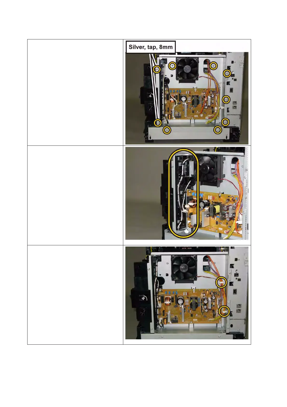
3) Secure the CHASSIS LVPS to the
printer with the seven screws (sil-
ver, M4, 6mm) and the two screws
(silver, tap, 8mm).
4) Route the harness of the HARNESS
ASSY FUSING UNIT MG AIO and
harness of the SWITCH ASSY
INLET MG AIO along the GUIDE
HARNESS LVPS.
5) Engage all the connectors of the
PWBA LVPS, secure the harnesses
using the two clamps on the CHAS-
SIS LVPS.
 Loading...