6 – 90
Chapter 6 General
(2) Engine Diag
- Sensor Test
This function checks whether the DI components operate normally or not.
The Sensor Test is performed for all the DI components.
Exit operation of the Sensor Test makes the control panel display the CE diag. function menu.
During the Sensor Test, other CE diag. functions can not be performed
simultaneouly. Therefore, the printer does not accept any operation except
operations for the DI components and exit operation of the Sensor Test.
At the start of the Sensor Test, number “ 0 ” is displayed on the control panel. This number is
counted up when a DI component is turned on from off, therefore it allows the user to know the
component is active.
When a paper jam is occurred, or an error message or code is displayed, execute this test to locate
the damaged parts.
The test will execute the Sensor Test codes of the components that are supposed to be faulty from
the error details. (Refer to each FIP on Chapter 1.)
Test result: NG (Go to each FIP or replace the parts.)
OK (Turn off/on the main power.)
- Executing Sensor Test
1) Turn off the power.
2) Turn on the power while holding down "" and "" keys.
3) Release the fingers from these keys when "the message" is displayed.
4) The "Service Mode", "Printer" and "FAX/Scanner" are displayed. (Entered the Diag. mode.)
5) Press "OK" key. (Entered the Printer Diag. mode.)
6) Press "" to select "Engine Diag", and then press "OK" key.
7) Press "" key to select "Sensor Test", and then press "OK" key.
8) Press "" or "" key to select the test item.
9) Press "OK" key twice to execute the test.
To exit the test press the "STOP" key, and to return to one step higher menu.
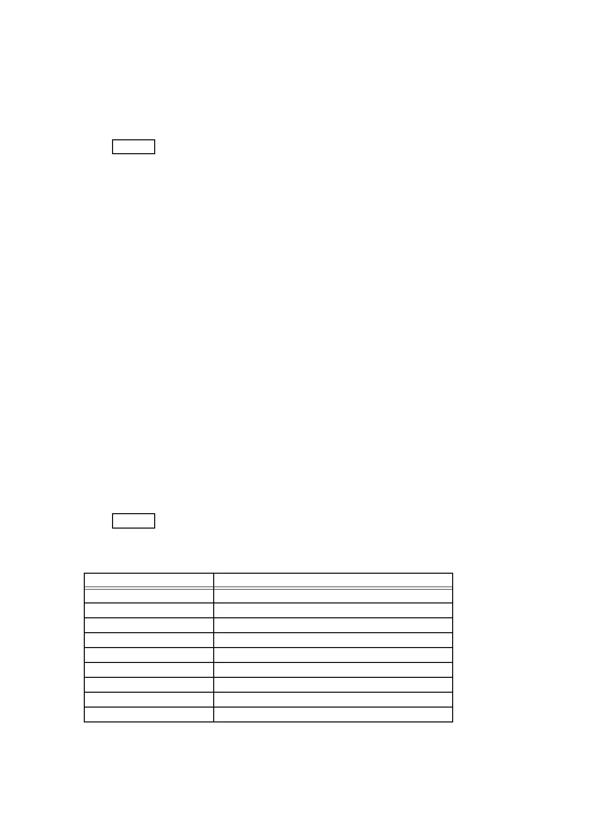
Parameters for the Sensor Test are as follows.
LCD Component
ManualFeedSensor
Manual Feed Sensor
Tray1 No Paper
Tray1 No Paper Sensor
Regi Sensor
Regi Sensor
Exit Sensor
Exit Sensor
K Mode Sensor
K Mode Sensor
Side Switch
Side Switch Sensor
CoverOpen Sensor
Cover Open Sensor
Tray2 No Paper
Tray2 No Paper Sensor
Tray2 PathSensor
Tray2 Path Sensor

 Loading...