Operation Manual – Management VLAN
H3C S3100 Series Ethernet Switches Chapter 1 Management VLAN Configuration
1-4
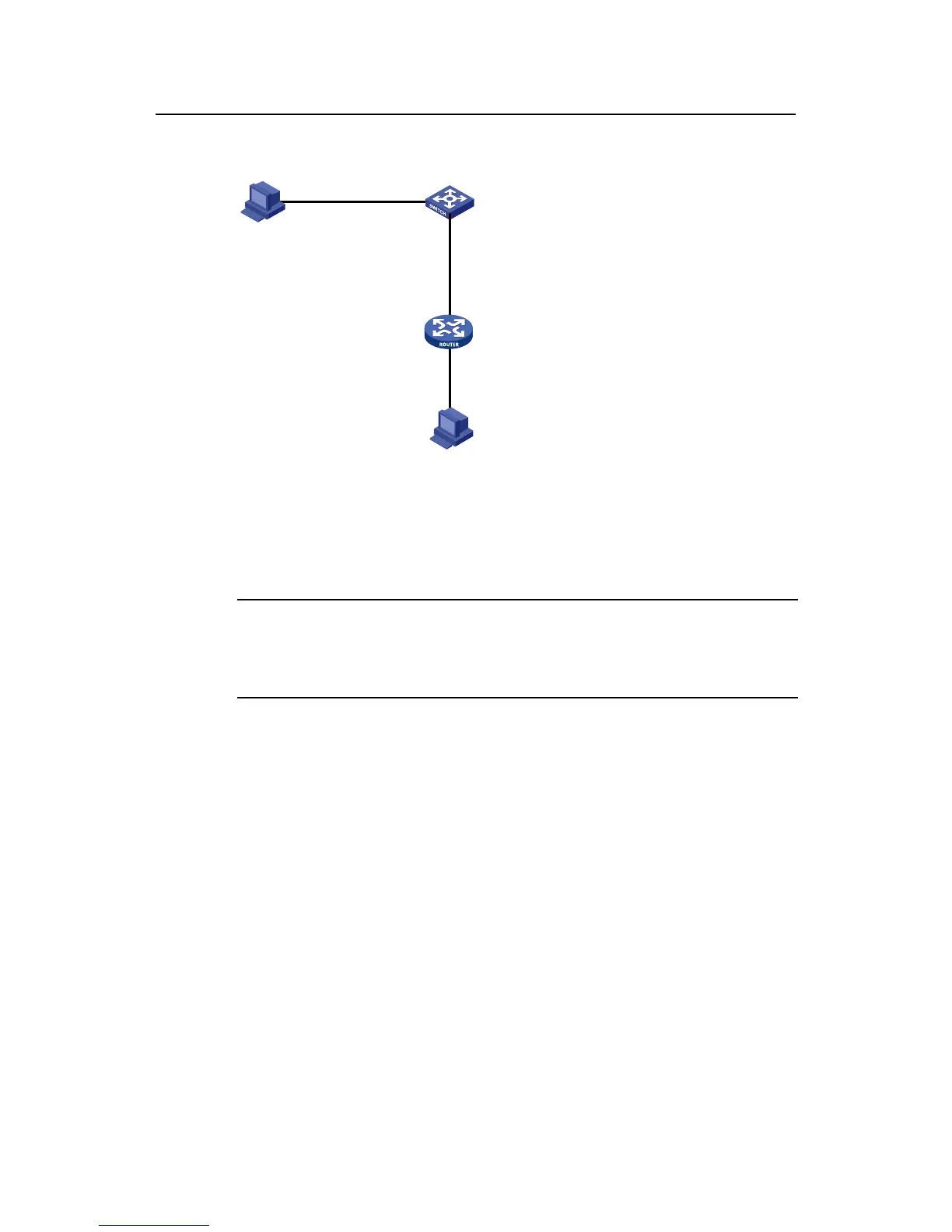
II. Network diagram
RS-232 serial
interface
Console port
Console cable
Vlan- interface10
1.1.1.1/24
Switch A
Telnet user
Ethernet1/1
1.1.1.2/24
Router
Current
user
Figure 1-1 Network diagram for management VLAN configuration
III. Configuration procedure
Note:
Perform the following configurations after the current user logs in to Switch A through
the Console port.
# Enter system view.
<SwitchA> system-view
# Create VLAN 10 and configure VLAN 10 as the management VLAN.
[SwitchA] vlan 10
[SwitchA-vlan10] quit
[SwitchA] management-vlan 10
# Create the VLAN 10 interface and enter VLAN interface view.
[SwitchA] interface vlan-interface 10
# Configure the IP address of VLAN 10 interface as 1.1.1.1/24.
[SwitchA-Vlan-interface10] ip address 1.1.1.1 255.255.255.0
[SwitchA-Vlan-interface10] quit
# Configure the default route.
[SwitchA] ip route-static 0.0.0.0 0.0.0.0 1.1.1.2

 Loading...


