Operation Manual – Smart Link-Monitor Link
H3C S3100 Series Ethernet Switches Chapter 1 Smart Link Configuration
1-8
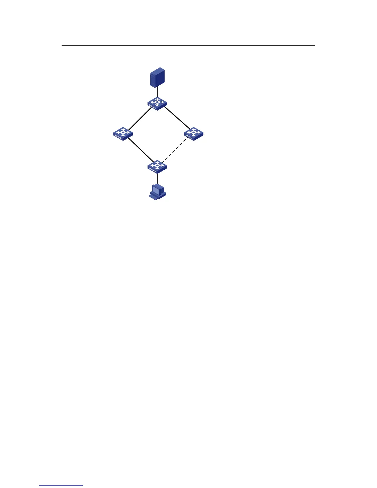
II. Network diagram
Switch A
Eth1/0/1 Eth1/0/2
Switch C
Server
Eth1/0/1
Eth1/0/2 Eth1/0/2
PC
Switch D
Switch E
Eth1/0/3Eth1/0/2
Eth1/0/1
Figure 1-3 Network diagram for Smart Link configuration
III. Configuration procedure
1) Configure a Smart Link group on Switch A and configure member ports for it.
Enable the function of sending flush messages in Control VLAN 1.
# Enter system view.
<switchA> system-view
# Enter Ethernet port view. Disable STP on Ethernet1/0/1 and Ethernet1/0/2.
[SwitchA] interface Ethernet 1/0/1
[SwitchA-Ethernet1/0/1] stp disable
[SwitchA-Ethernet1/0/1] quit
[SwitchA] interface Ethernet 1/0/2
[SwitchA-Ethernet1/0/2] stp disable
# Return to system view.
[SwitchA-Ethernet1/0/2] quit
# Create Smart Link group 1 and enter the corresponding Smart Link group view.
[SwitchA] smart-link group 1
# Configure Ethernet1/0/1 as the master port and Ethernet1/0/2 as the slave port for
Smart Link group 1.
[SwitchA-smlk-group1] port Ethernet 1/0/1 master
[SwitchA-smlk-group1] port Ethernet 1/0/2 slave

 Loading...


