Chapter 3 ’Web User Graphical Interface’ — GUI Description
Electra VS
-
Version 05.10 169
User Manual - Rev. A
In each Network interface profile, you can link the physical interfaces to
a logical interface declaring its name, you can define the bonding and if
alarms shall be raised when the link is down.
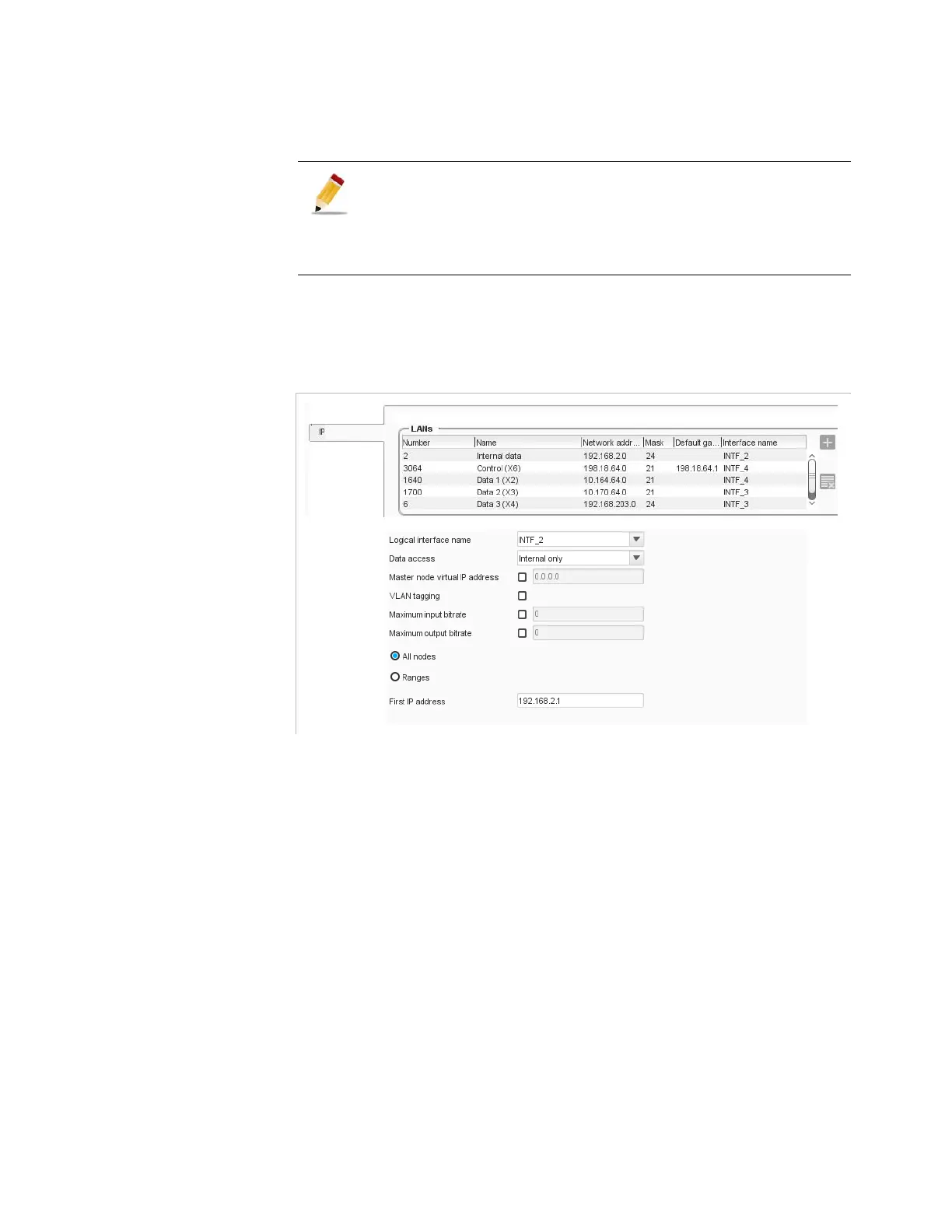
LANs
Figure 3-127. LAN configuration
For each LAN the table displays the following processing components:
Number
: number of the LAN, used to identify the LAN in logs.
Name
Network Address
Mask
Default gateway
Logical interface name
When selecting a LAN, additional parameters are displayed on the right:
Logical interface name
: logical interface to connect to this LAN.
The logical interface names are in bold if available on all the nodes
linked to the LAN. Otherwise you will have to modify the network
interface profiles to give an acces to the LAN to the missing nodes. For
more information on blade interfaces, refer to
Appendix F ’Network
Settings’
on page 573.
About Hardware delivery (1RU, 6RU, 10RU platforms):
An 1RU platform can be associated with another Network
interface profile. On the other side, the Network interface
profile of a blade in 6RU or 10RU platforms can not be
changed.