Chapter 3 ’Web User Graphical Interface’ — GUI Description
188 Electra VS
-
Version 05.10
User Manual - Rev. A
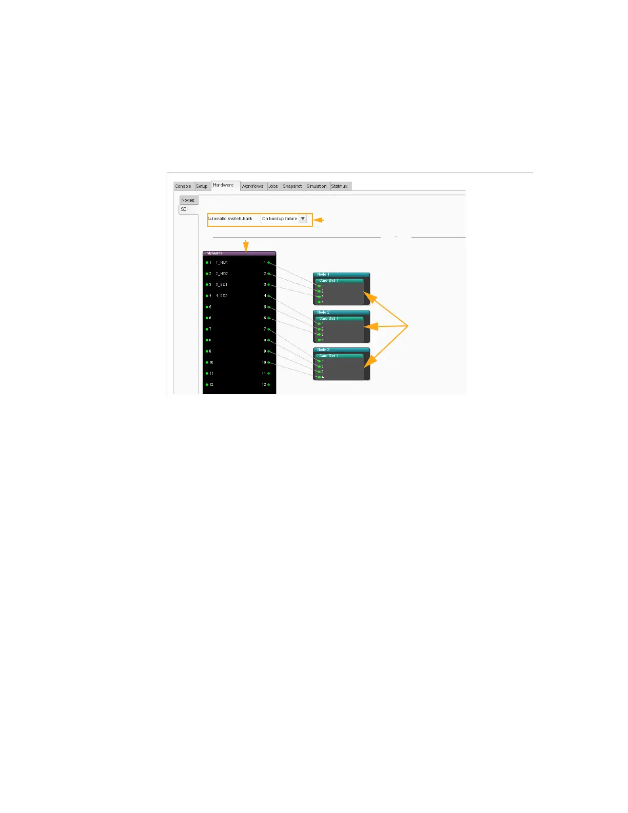
Hardware/SDI Panel
The
SDI
panel provides a representation of nodes and SDI cards in the
system and lets you configure SDI matrices and Redundancy mode to
manage redundancy.
Figure 3-147. SDI panel
SDI Cards
The nodes that contain SDI cards are represented. The slot in which the
SDI board is installed is indicated.
You can double-click the board to name it and give a name to the sources
connected on the inputs. This will ease configuration when creating
workflows and jobs.
SDI Matrices
If you have a matrix in the system, you need to declare it in this view. The
list of supported SDI matrices is available in
Table A-60
on page 515.
The GUI displays a representation of the matrices declared in the Electra
VS equipment.
To find out how to declare a matrix, refer to section
’Configuring an SDI
System’
on page 149.
You can right-click a matrix processing component to access the
following actions:
Properties
: lets you see the properties defined when creating the
matrix.
SDI cards
SDI matrix
SDI redundancy mode selection