Appendix F ’Network Settings’ — Hardware Delivery - 6RU and 10RU devices
Electra VS
-
Version 05.10 575
User Manual - Rev. A
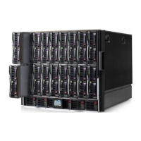
6RU Device
Each blade has 16 network interfaces. On the Flex10, they are named
LOM:1-a to LOM:8-a and LOM:1-b to LOM:8-b;
a
blades being on the first
Flex10 and
b
blades on the second one.
On the 6RU device, associations between interfaces in the software
application and the FlexNIC in the Flex10 are defined as follows:
Interface 1: LOM:1-a & MEZZ1:1-a
Interface 2: LOM:2-a & MEZZ1:2-a
Interface 3: LOM:1-b & MEZZ1:1-b
Interface 4: LOM:2-b & MEZZ1:2-b
Interface 5: LOM:1-c & MEZZ1:1-c
Interface 6: LOM:2-c & MEZZ1:2-c
Interface 7: LOM:1-d & MEZZ1:1-d
Interface 8: LOM:2-d & MEZZ1:2-d
VLAN Tagging
When using VLAN tagging to have more than four interfaces in total in
the 10RU device, or eight interfaces in total in the 6RU device, it is
imperative that the configuration be consistent with the Flex10
configuration.
Internal Switches & Software Configuration
Consistency
The configuration of the blade internal switches (Flex10) must be
consistent with the network configuration in the software application
Here are the main configuration principles:
Interfaces 1 are reserved to the system network of the blade center, for
management.
In the software application, it is possible to define networks of
internal
data
and
external data
.
On the Flex10:
A
private network
forbids the dialog between two blades of the
blade center.
Internal data
networks and the
System
network must never be
set as
private network
.